
Create a Triangulated Surface from Points
Use this activity if the external drawing file or point file does not include a triangulated surface. See Load an External Drawing File.
The lines and points represent a real landform. A triangulation is a gridded, continuous, digital mapping of a terrain based on those points. The triangulation interpolates data between the surveyed points. The accuracy of the triangulation depends on the density of the surveyed points.
Activity Steps
- Select the Design module.
- Open the set of design lines or surface in maintenance (edit) mode. See Edit a Set of Design Lines or Edit a Surface.
Note: Use the View Toolbar to rotate the drawing so that you are viewing it from a similar line of sight as the equipment used to survey the points in the topography. Viewing the diagram from the front may result in an unexpected triangulation.
- On the CAD Tools Ribbon Menu, in the Surface Manipulation group, click Create Surface.
- Select one or more groups of points:
- Click the top-left corner.
- Click the bottom-right corner.
Points within the blue rectangle are selected.

- Right-click or press Enter to complete the selection.
DataBlast Ignite calculates and displays the triangulation of the selected points. The View toolbar includes an option to toggle between the render mode, shade mode and the wire-frame mode of the triangulation.
The following screenshot displays an example of a triangulated surface in 3D wire display mode.

The following screenshot displays the same surface in render or shade mode.
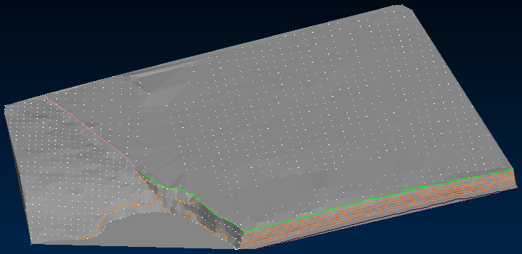
Render display mode is identical to the shade display mode when there are no texture images on the 3D mesh. Texture images come from importing PLY, OBJ, DM or DMX files that have texture-images associated. Texture images are the MTL, JPG or PNG files in the same folder as the mesh file which itself contains references to the texture images. In this example, there are no texture images.