Alpha/Beta Angles
Use the Alpha/Beta tool to calculate the orientation of:
- Discontinuities and geological structures from the alpha and beta core angles of the discontinuity
- The drillhole at the location of the discontinuity
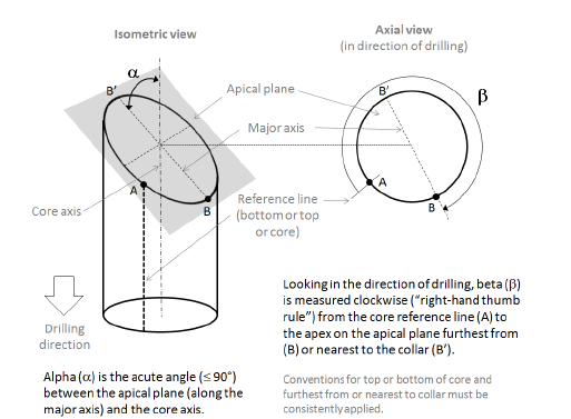
Referring to the diagram below, the discontinuity surface forms an ellipse, referred to as the "apical plane", with apices at either end of the major axis of the ellipse.
The alpha angle is the acute angle of intersection between the apical plane and the core axis measured along the major axis of the ellipse (BB’). The alpha angle is always a positive angle between 0° and 90°.
The beta angle is measured clockwise looking in the direction of drilling (the right-hand thumb rule) around the circumference of the core from the top-of-core or bottom-of-core reference line (A) to the apex furthest from (B) or nearest to (B’) the collar.
The measuring convention (bottom or top of core and nearest or furthest apex) must be consistently applied on all drillholes. The diagram shows the furthest from convention.

Measuring alpha and beta core orientation angles showing bottom-of-core reference line (A) and apex furthest from collar (B).
Note: Take care to ensure that the alpha and beta angles are measured as shown in the diagram above and whether the reference line is scribed at the top or bottom of the core. Practice does vary; for example, the alpha is sometimes measured as the angle between the normal to the apical plane and the core axis, that is, 90° – alpha.
Before alpha-beta structure data can be displayed on a drillhole trace, the file must be converted into a standard structural data table with dip and dip direction fields.
The Alpha/Beta tool converts structural downhole data points defined by alpha and beta angles into dip and dip direction angles. Before using this tool, check that:
- The structure table has (at least) HoleID, Depth From, Depth To, Alpha, and Beta fields. The field names in the structure table must match the corresponding field names used in the project.
- The Depth From value is equal to the Depth To value (forming a surface of zero thickness, such as a joint or bedding plane) or greater than the Depth To value (forming an infilled structure, such as a shear or fault). The apical plane is defined at the midpoint of the from and to depths.
- The Alpha and Beta fields are numeric. If present, Dip and Dip Direction fields must be Float type.
- The Alpha and Beta values have been measured according to the convention defined in the diagram above.
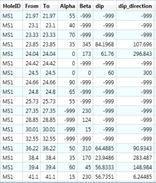
Note: Zero is a valid value for alpha and beta values and is treated as a zero angle (not as a null value). When the file is processed, if zero values are detected, the number of records with zero values is reported, and you are asked to confirm before proceeding to process the file.
Note: If the data is imported in CSV format from a Microsoft Excel spreadsheet, Excel converts blank cells into zeroes. To preserve null values, enter –999 in all blank cells before saving as a CSV.
Null dip and dip direction values are outputted if:
- Either the alpha or beta value is null (-999).
- The alpha value is greater than 90 or less than zero.
- The beta value is greater than 360 or less than zero.
The following example illustrates where the alpha/beta structure table shows zero and null values.


