
Tube Wireframes
Stope quadrilaterals form a tube-shape when extruded in the transverse direction representing the stope-shape W-axis. For the Slice Method, the stope shapes are constrained to the tube geometry when extruded in the transverse direction (W-axis). The face or projected wall shape will be defined by the four corners in the wall plane (hangingwall/footwall or near/far wall for vertical orientation, roof/floor wall for horizontal orientation).
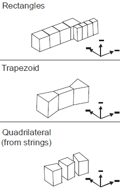
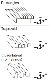
The shape of the tubes can be rectangular or trapezoidal or based on quad strings and will depend on the orientation of the framework and whether it is of the standard or advanced type.
Here are some examples of the type of tube wireframes MSO can create for a horizontal irregular framework:
In comparison, tube shapes for a vertical irregular framework (for the same input data) could be:
The stope-shape tube volumes are defined by framework options and optional control-string combinations.
Related topics and activities