
|
|
Explicitly modelling surfaces between sample points |

Wireframes from Drillholes
To access this dialog:
-
This dialog is accessed by running the wireframe-explicit-from-drillholes command. This will display the Wireframes from Drillholes dialog.
This topic includes the following sections:
- Wireframes-from-drillholes: Command and Dialog Overview
- Data Selection and Pre-selection
- Input Sample Data - What is Expected
- About Data Uncertainty
- Positive and Negative Samples: Covariance
- Negative Sample Influence
- Minimum and Maximum Thickness Settings
- Modeling Hangingwall and Footwall Surfaces
- Boundary Shaping Options
- Wireframe from Drillholes vs. Create Vein Surfaces
- Intermediate Files
- Wireframes from Drillholes dialog: Field Details

Wireframes from Drillholes: Functional Overview
|
|
This command will only be able process unfiltered data samples. If you wish to model all of the positive values in your input data, you will need to clear existing object filters beforehand. |
The Vein Modelling tool is used to model hangingwall (HW) and/or footwall (FW) surfaces that honor input drillhole sample values. These values will normally represent a vein or vein-like structure, with a discrete upper and lower bounding surface. Optionally, model a closed volume representing both HW and FW surfaces and control how surfaces interact in pinch and/or swell zones.
This function models interpolated structures using FROM-TO values within the input sample data set, which will be a static drillhole file.
|
|
Data from this command and dialog will be output as in-memory objects. To save output data to a physical file, use the Sheets control bar, or any of the data export/save commands on the Data ribbon. |
Surface calculation between samples is influenced by controls that impact:
-
your choice of surfaces to create (Hanging wall, Footwall or Both).
-
Clipping boundary, which determines the boundary where the vein terminates. The extent/range of samples that determine interpolated surface vertices (using a search radius).
-
The 3-dimensional grid in which surface data is computed (Resolution).
-
Minimum (with choices of expand to or remove below) and maximum thickness, for extending the vein to the chosen clipping boundary.
-
Whether negative samples will be considered to create pinch-outs around drill hole interceptions that do not contain the vein code.
-
The Trend smoothness of the surface, which determines how wavy the resultant surface will be (Gaussian method only)
Considerations for deciding the above may include:
-
Your confidence in the input data.
-
The amount of positive samples that exist, and the density of those samples.
-
The geological properties of the domain environment.
-
Other supporting media such as seismic analysis, historical data, geophysical properties of the domain etc.
-
Whether a relatively conservative or generous outcome is required.
From the input sample set, one or more 'positive' (non-absent) intervals will be derived, around which a HW (FROM) and/or FW (TO) surface will be constructed. The shape of these surfaces is influenced by other samples in the vicinity and the settings in the Create Vein Surface dialog.
|
|
If you have a lot of sample data on screen, it can be difficult to get a clear view of the positive intervals, even with Auto Look enabled. You can remove all negative intervals from the screen using the Quick Filter control bar:
|

The resulting shape(s) will be constrained by 'negative' samples (those that do not match the selected key field and value), if they exist within the selected input sample set.
You can model either a HW or FW surface, or both. If both, you can choose to either create two separate surfaces or a closed volume representing both.
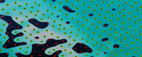
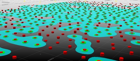
A cuboid grid is formed around the hull of the positive samples. The points in this grid will be set to a given elevation, depending on the locality and power of samples in the input set, how continuous you choose your surface to be and other controls.
The grid will, by default, be positioned outside the exterior hull of the positive sample points, around the extents of the input data and additional pointsIt is this matrix of points within the grid that will be used to create 3D surface points at calculated elevations using interpolation between known sample points.
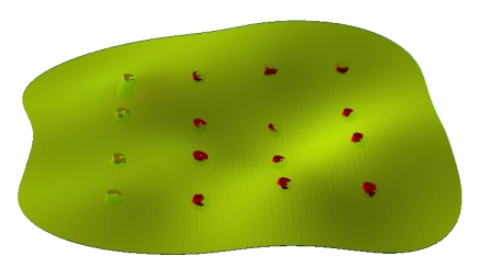
For example, the red sample in the image below is exerting an influence over other grid point values as a function that decreases from the distance from its position. This will influence the elevation value for the computed mean, hangingwall and/or footwall surface at each location.
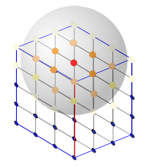
Which points are considered depends on the location of nearby samples (positive or negative) as those that fall within a defined radius will be considered. Points that are considered will influence the interpolation according to the power of those samples. Other contributing factors such as the Minimum thickness and clipping options are also involved.
|
|
If you have created multiple vein volumes you wish to represent in a block model, use the model-from-multiple-wireframes command to rapidly generate a full- or sub-cell model of your structures. More... |
About the Output Wireframe
An output wireframe, either HW, FW or combined volume will include all standard fields in both the triangles and points file. The output triangles file will also include the Field attribute and corresponding Value for each modelled structure. The vein-from-samples command utilizes a trend surface to guide the construction of HW and/or FW points.
Data Selection and Pre-selection
A static drillhole data set must be loaded into memory to use this command.
If no drillholes are selected, all holes within the loaded data object are considered.
Alternatively, you can preselect the samples you wish to use. You can do this using Studio's existing selection methods (left-click, CTRL, bounding box) and this can be performed whilst the modelling task window is displayed.
Sample selection, if performed, accommodates both positive and negative samples: only selected data influences either the generation or retardation of the resulting surface/volume.
If drillholes are pre-selected, at least two individual samples must exist within the selected set. If only one is selected, you are informed that a different selection must be made.
Input Sample Data - Overview
Input static drillhole data must contain at least one attribute (alphanumeric or numeric) defining samples to be modelled, and for one or more valid key field values to exist for that attribute. Where a value exists for the selected attribute, each FROM-TO interval will define the "positive samples" that will serve as landmark points for the construction of the HW and FW surfaces (and potentially the volume representing both).
Only one sample attribute can be modelled at a time.
The image below shows an artificial positive sample set and no other data. Samples are equidistant - but not orthogonally to the trend plane of the data:
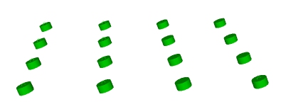

In this situation, the Vein
Data Uncertainty - Sample Confidence
Uncertainty - Sample Confidence
For more information on managing data uncertainty, see Snapping to Contacts
Positive and Negative Sample Influence
A Minimum Curvature method is used to construct a surface between known HW and FW sample positions.
This is the default surfacing option and differs from the Gaussian method by the calculations involved in projecting surface data between points. The concept of covariance isn't relevant to Minimum Curvature calculations (see the Gaussian Method Surface Calculations below, by comparison).
The vein modelling tool will also assume a zero uncertainty with this method.
The Influence of Negative Samples
Where samples exist that do not include an interval that matches the selected key field and value, they are considered negative.
Negative samples work in tandem with positive samples to control the shape of the resulting surface or volume. They exert an opposite but equal influence over shape generation as positive samples.
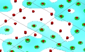
Consider the following positive-only sample set, comprising 16 samples:
With the same settings, introducing a negative sample into the set causes an intrusion into the structure:
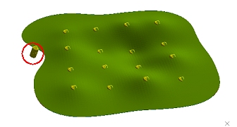
The negative sample exerts an identical influence over the modelled
surface as all of the positive sample points, although the final shape
of the structure can be further controlled by other parameters, including
boundary clipping
settings and the overall arrangement of samples.
Minimum and Maximum Thickness Settings
Thickness limit settings will have an influence over the extents of your structure and internal continuity.
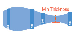
The Minimum thickness parameter is only applied if you choose to Pinch out and Both HW and FW surfaces are generated, the Minimum thickness setting allows you define a distance below which the structure is pinched out. Pinching out is performed by tapering the HW and FW surfaces to force them to converge.
-
In the vein-from-samples command, you can choose to administer a minimum thickness in two ways; either to force a pinch out below a given thickness (= anything below a thickness value is removed) or you can expand the structure to adhere to a minimum value, forcing continuity.
"Remove Below" Mode
In this mode (which is the default for the vein-from-samples command), setting a higher Minimum thickness will produce a smaller and potentially more fragmented structure, although this will depend on the inter-sample spacing and the interval lengths of positive samples.

Setting a Minimum thickness to zero will allow HW and FW surfaces to converge and align, although if they are calculated as overlapping/inverting they will still result in a pinch out if the Pinch out option is selected. Otherwise, they can get as close as they like.
Continuing the example above, increasing the Minimum
thickness generates a more restricted boundary as the HW and FW
surfaces converge down to the thickness value at a point closer to the
sample intervals:
In the final image, the HW and FW surface in the lower right quadrant (as viewed) dips below 0.75 so is pinched out.
Setting a Maximum thickness will cause HW and FW surface to be adjusted so the maximum limit is not exceeded. This can be useful to control unexpected swells where neighboring sample intervals are very different.
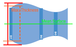
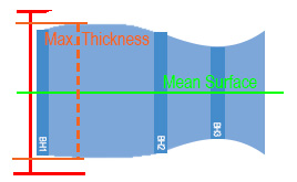
During Max thickness adjustments, the HW and FW points are adjusted proportionally in relation to their distance from the mean surface.
"Expand To" Mode (vein-from-samples command only)
In this mode, your structure will be expanded to a specified thickness value if the calculated mathematical trend of the HW and FW surfaces would ordinarily provide either a crossover or a thickness that is lower that the specified amount.
Consider the following Gaussian example (which compares the Remove Below and Expand To options):
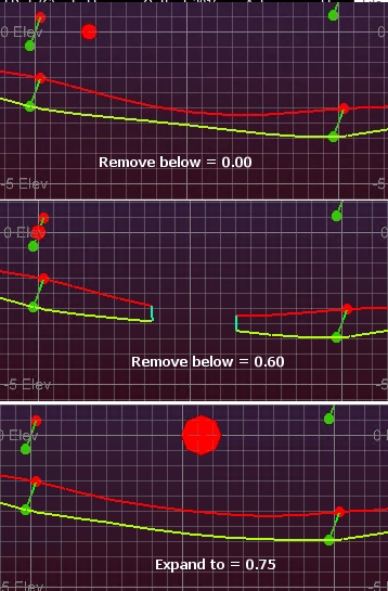
In the lower image, you can see how the HW and FW surfaces are pushed apart to satisfy the minimum requirement of 0.75m. This expansion is applied before negative sample influence is applied; voids will still occur where a negative sample intercepts a structure, pinching it out.
Modelling Hanging wall and Foot wall Surfaces
You can model either HW or FW surfaces as DTMs, or both surfaces as a closed volume. The default is to generate a volume, which can be fed into downstream processes such as grade/tonnage calculations and cell/subcell modelling.
You can 'pinch out' data by selecting Pinch Out, but only if you are creating a closed volume comprising both HW and FW surfaces. This allows you to model pinch zones within your modelled surface where one of these conditions are met:
- A negative sample (a sample that intercepts the predicted path of the vein but does not contain the geological unit that is being modelled) intercepts the vein. This indicates that there is an absence of the vein in this area, and a pinched out hole will be modelled in that area.
- The thickness of the modelled volume is less than a designated value. For example, if you wish to obviate vein data that is less than a mineable limit, you can set this Minimum thickness (see above).
The HW surface will always be formed on one side of the trend surface and the FW surface on the other.
The distance of the HW and FW points from the trend surface at each grid point is calculated by interpolation, honouring other factors.
Boundary Shaping - Additional Clipping Options
You can control the boundary behavior for your surface(s) using one of the provided Clipping options.
-
Aligned Square: use a bounding cuboid to restrict the surface hull. The cuboid hull will include all positive samples and will be extended beyond this by the defined Extension Distance.
-
Radius: restrict surface generation at a given Extension radius from a positive sample, regardless of other settings.
-
Radial interp: for each sample, generate a bounding circle of a given Extension radius and use bounding arc segments to construct an external edge.
-
Alpha shape: use a specified segment length to determine the alpha shape of the exterior hull. Depending on the specified segment length, a more or less generalized outline will be produced.
These allow you to control how the outer edge and internal voids of your modelled lode are calculated.
More about boundary clipping options...
Wireframe from Drillholes vs. Create Vein Surfaces
Just like the wireframes-explicit-from-drillholes command, vein-from-samples utilizes a mean surface to guide the construction of HW and/or FW points.
With the vein-from-samples command, a mean surface is created automatically using default values.
Unlike the wireframe-explicit-from-drillholes command, vein-from-samples creates an interim mean surface in the same operation as creating the HW and/or FW surfaces, and does so automatically using default values.
With both commands, you can create a mean surface object in memory, which could be saved to disk for investigation, such as determining anisotropy within the sample set, for example.
Once you have defined input samples and parameters, click Compute Surface to generate a surface, surfaces or volume.
As the functionality within the Create Vein Surface dialog has a partner function in the Wireframes from Drillholes dialog, the Field Details section below maps functions between each function.
All outputs possible with the Create Vein Surface dialog are also possible with Wireframes from Drillholes. The latter has additional functionality for managing edge cases and unusual inputs, and can be used to generate intermediate structures for HW and FW surfaces.
The Wireframe from Drillholes command exposes the full range of explicit surface modelling functions, and in most cases, the range of options presented will be left in their default state.
A streamlined version of this command, focussed on the formation of vein surfaces, is also available in Studio and is likely to be the place vein modelers spend their time. Vein-from-samples utilizes a subset of the full set of commands described here, and is likely to be adequate for the vast majority of vein modelling projects.
Both vein-from-samples and wireframe-explicit-from-drillholes utilize the same surface generation 'engine', although how controls are described will differ in some cases.
Wireframes from Drillholes is suited to modelling edge cases that may require granular control over the intermediate steps of surface generation (more information on this below) or requires a more precise control over how hangingwall and footwall surfaces are generated (e.g. the base algorithm used).
In summary;
- Wireframe from Drillholes contains all of the functionality of Create Vein Surfaces plus additional controls.
- Create Vein Surface is a quick and easy portal for vein modelling that will suffice for the majority of sample configurations and lode types.
For volume calculations, even if you choose to Compute intersections (= pinch out where overlaps occur or less than the minimum thickness is achieved), you can still generate "pre-pinchout" surfaces for inspection.
This is done by enabling Produce Intermediate Files before you select Compute Surface. These files have standard names, but can be renamed using the Sheets control bar afterwards:
- HangingWallWFPrePinchout: this is the HW surface before any pinching out has taken place, or a boundary has been calculated. It will pass through the FROM position of the positive sample, within the limits set by the uncertainty for the data set or sample.
- FootWallWFPrePinchout: as above, but this surface transects the TO interval position within any Uncertainty tolerance.
If you choose to create intermediate files, the pre-pinchout HW and FW surfaces are generated when you Compute Surface. The gaussian mean surface is also created, but when you Update Mean Function.
If intermediate files already exist in your project, you will be
prompted to overwrite them
.
Wireframes from Drillholes - Field Details:
The following options are available for the Wireframes from Drillholes dialog.
Data Selection:
Drillholes: select a loaded static drillholes object containing samples to be used for surface construction.
Field: select the attribute containing the values to be modelled.
Value: select the key field value that represents the surface to be modelled.
Uncertainty: if your sample file contains an uncertainty attribute, select it here, otherwise the Default uncertainty will be used for all samples. If a value is selected, the Default uncertainty will be used for all absent data values.
Surface to Generate: choose from either HW or FW or both. If both, you can optionally merge these surfaces and/or compute pinch zones (see below).
Type: select the covariance method to be used when generating either mean surface or HW/FW surfaces, or both.
A [Matern] type is available as a default.[Normal] and [Polynomial] methods are also available.
More about surface types...
Calculate Parameters: calculate appropriate radii for both mean and Covariance functions (see below).
Produce Intermediate Files: select if you wish to create:
-
a gaussian means surface when Update Mean Function is selected.
-
Pre-pinch out HW and FW surfaces (if generated) when Compute Surface is selected.
More about intermediate files...
Mean Function (more...):
Radius: specify the search radius to be used to generate a mean surface.
Power: determine the power of the samples that will influence inter-sample mean surface creation. Generally, the default will suffice.
Update Mean Function: this will generate the gaussian mean surface that will be used to guide HW and FW creation. This will also update the summary details box above, which calculates the volumetric centre of mass of the sample set and the mean normal direction.
Covariance Function (more...):
Radius: specify the search radius to be used to generate HW and FW surfaces. This should represent the distance from your samples (positive and negative) over which a sample has influence within the cuboid grid.
Power: determine the power of the samples that will influence inter-sample surface creation. Generally, the default will suffice.
Percentage extra: a % figure that will extend the automatically calculated bounding cuboid (containing N Grid points) outwards by a given proportion. It may be necessary to increase this figure if input samples are sparse and widely spaced.
N Grid: a value controlling the resolution of the points within the bounding cuboid (N x N x sample set height). A higher number will result in more dense wireframes but will take proportionally longer to calculate surfaces.
Note that this is an absolute value - it does not increase with sample set size.
Minimum thickness: the distance below which a pinch out will be applied if Compute Intersections is selected, and both HW and FW surfaces are generated together.
This setting is only valid if both HW and FW surfaces are being generated together.
Compute intersections: if enabled, the intersection between HW and FW surfaces will be computed to create pinched out areas where the surfaces either invert or fall below the Minimum thickness (see above).
Output:
Hanging
wall:
the output file name for both HW-only outputs and merged volume surfaces,
where Merge surfaces is enabled.
You can either select an existing loaded data object or enter a new
output object name. You will need to confirm overwrites of existing
data.
Merge surfaces: if HW and FW surfaces are being generated, enable this option to create a single enclosed volume. Disable to produce two separate surfaces.
Foot wall: for FW-only outputs, this field can be used to select an existing object or enter a new output name.
|
|
Related Topics |
|
|
Create
Vein Surfaces
wireframe-explicit-from-drillholes vein-from-samples Mean Surface Calculations Boundary Clipping Implicit Surface Types |
Copyright © Datamine Corporate Limited
JMN 20045_00_EN