
Matching Surface Triangulation
Note: This topic relates to the way DTM surfaces are created and how this can impact the use of cut and fill volume and tonnage calculation tools.
Studio Geo provides a wide range of tools for wireframe surface creation and manipulation.
When calculating extraction volumes and tonnages, "cut and fill" functions are particularly useful. These tools calculate the amount of material extracted in a time period, using a "current" and "previous" surface to understand what has been mined and where. Optionally, a reference surface can be provided, which can also be useful to understand how you are progressing against the scheduled end-of-period surface or designed pit phase shell.
Extraction amount and 'depth' varies across an extraction volume, and in some cases, the difference between the previous and current surveyed surfaces can be considered trivial. For this reason, cut and fill (and other commands that automate cut and fill, such as Studio Survey's EOM reporting tasks, for example) allow you to ignore volumes that fall below a certain threshold, either as a 3D volume in cubic measurement units) or as a true thickness below which to ignore data fragments.
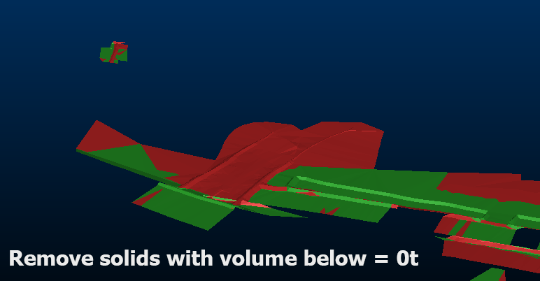
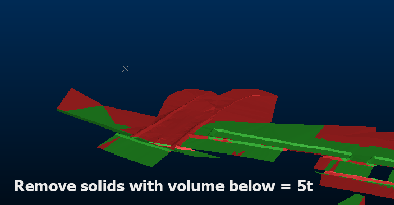
Cut and fill outputs showing overbreak/underbreak with and without fragment removal
These fragments can also occur when previous and current surfaces have not been mined, which at first seems nonsensical and buggy. Actually, these tiny fragments can also arise between the different triangulation that occurs between coincident surfaces.
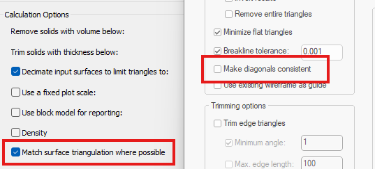
You can remove these using the fragment removal tools available in cut and fill and other tools, but in the case of triangulation mismatches, these can be largely avoided using the Match surface triangulation where possible (Studio Survey EOM reports tasks) or Make diagonals consistent (Make DTM tool) options.
Enabled by default, triangulation between surfaces used (in this case, for cut and fill) remains consistent in unmined areas, avoiding the change of trivial data fragments.
Another option is, when you are creating DTMs (for any reason, including as an input to cut and fill operations) you can select a wireframe and use that as the basis for 'default triangulation'. Where the generated DTM surface and reference surface then coincide (within a small tolerance) the triangulation of the reference surface is applied to the DTM. This means that your DTM inputs to other functions will have known coincident vertices and edges where the surfaces coincide.
You can access this option on the Create DTM screen as Use existing wireframe as guide. Later in the wizard (after selecting input points/strings and, optionally, boundary data, you can then pick any loaded wireframe object as a reference surface.
Related topics and activities: