|
|
Project Settings - Digital Terrain Models DTM properties and functions |
Digital Terrain Model Settings
To access this dialog:
-
In the Project Settings dialog, select the Digital Terrain Models tab.
A digital terrain model is an open wireframe mesh, normally used to intimate the presence of a topographical surface, although it is also used to denote fault planes or any other planar geological domain. To use this command, at least one string object must exist in memory.
|
|
DTM Creation Setting defaults are also set on a 'one use' basis, using the Make DTM dialog. Settings made here will be shown by default in this dialog when it is launched. |
Use boundary strings: if selected, this will introduce a third (and final) screen to the Make DTM wizard, in which you will be prompted to specify a string file that demarks the positions of a mesh boundary. All data outside of this closed string will be removed from the resulting DTM object.
Any number of boundary strings can be specified, with the system using the left-to-right rule to determine whether the string is an outer or inner limit. By default, the first string encountered will be assumed to be an outer limit, then the next, an inner limit and so on. There can be multiple outer limits, and multiple inner limits within an outer limit. Where the first string defines the inner limit (e.g. there is only one string), choosing Invert Results will reverse this left-to-right logic.
Minimize flat triangles:
when generating a mesh from contours, facets may connect to the same
contour line. Selecting this option will perform a pass after the
initial tessellation to flip connections to minimize this effect.
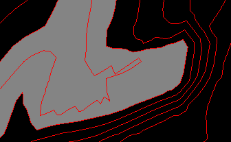
The effect of this setting can be hard to visualize, but is best described
by means of an example. The following image shows a magnified section
of a topographical contour string file. The area highlighted in grey
represents the area where most 'decision making' must be made by any
surfacing routine, due to the multitude of options for connecting
separated vertices:
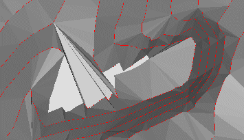
In this situation, settings made in the Make DTM dialog will have a significant effect on how the DTM is generated in this area. If the Minimize Flat Triangles option is selected, connections to the same contour line will be minimized. Following the above example, this would result in a surface similar to the following:

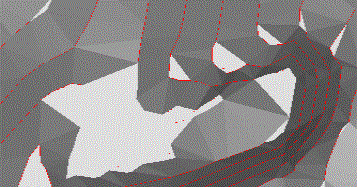
Whereas, if no attempt is made to eliminate triangles sharing the same alignment, connected to the same facet, the result in this case would be similar to the following image:

Breakline tolerance: honoring breaklines (that is, the positions of string vertices) unequivocally when generating a DTM wireframe can lead to degenerate sliver triangles. The extent to which this may occur will depend on the position and density of initial string triangles. Opting to include a Breakline Tolerance will allow these positions to deviate by the specified amount to minimise this effect.
DTM Plane: although most DTM models will be generated relative to the virtual world's XY plane, there may, at times, be a requirement to create a surface in a different orientation (e.g. along a drive). In this case the current view plane, as determined by the viewing direction in the design view, can be used to specify a DTM projection plane. Choose Plan for the world XY plane, and View for the current view plane. Alternatively, the Best Fit option will attempt to calculate a plane which best fits the points being input to the DTM function.
Trim edge triangles: a convex hull created by the DTM process may contain thin 'sliver' triangles. Opt to Trim Edge Triangles to have these recursively removed from the edge of the wireframe until the specified parameters have been satisfied. Once selected, the following options become available:
-
Minimum Angle: remove any triangles which have a vertex angle less than the user-specified minimum.
-
Max. edge length: select this option to remove any triangles with an edge longer than a specified amount.
Spur Options: when generating DTMs from a series of contours, plateaus can often be created on the upper or lower contours. Spur strings can be used to minimise this effect by using interpolation of the surrounding slopes to extend the gradient past the plateau level.
-
Generate crest spurs: create and use crest spurs. Adjust Crest Heights By would be a positive number to increase the crest elevation
-
Generate valley spurs: create and use valley spurs. Adjust Valley Heights By would be a negative number to reduce the valley elevation.
-
Generate key spurs: create and use key spurs.
-
Output spur Objects: to see the spur strings which were generated for use within the DTM creation, choose the Output Spur Objects option, which will output spur strings a new strings object. The type of the spur (Crest, Valley, Key) will be stored in its TYPE attribute.
Attributes: there are three different ways to define the attributes which will be contained within the DTM.
-
Use First Point/String: copies all the non-system attributes from the first string or point encountered when generating the DTM. The precise string or point is essentially undefined, so this option is primarily intended for copying general attributes where the input strings share a common set of attributes (e.g. colour).
-
Use All Points/Strings: post-processes the DTM and attempt to match each point (or string vertex) to any wireframe triangles which shares the vertex, and will then copy all non-system attributes to those triangles.
-
User-Defined: allows the Edit Attributes dialog to be used to define the attributes and values which will be used in this DTM link. By default, the attributes and values in the Edit Attributes dialog will be from the output wireframe, but the Pick Button can be used to select any point, string or other item in the Design window to prime the attributes to be used in the DTM.
|
|
Related Topics |
|
|
The Project Settings dialog |

