|
|
Projecting string or point data to a wireframe surface or Section |
To access this dialog use one of the following:
-
Run the command 'project-points-to-wf' or 'project-string-onto-wfs'
-
Use either the quick key 'pptw' (points to wireframes) or 'pstw' (string to wireframes).
The Project Strings/Points dialog is used to project selected point or string data onto a specific wireframe surface(s) and/or Section. The existing object can be updated (that is, the positions of points or string vertices are updated) or a new object can be created to store the projected data. All available wireframe surfaces are available for selection, as are any available section objects. A variety of options are available for controlling the projection direction.
Field Details:
Output: choose from one of the following options:
-
Update Existing Positions: modify the currently selected object so that all vertices and points are projected to intercept the selected wireframe object(s) in the specified direction. Note that this will update the string object in memory, and therefore update the view of the string or points in all available views, including the Design window and Plots window.
-
Output to Object: to output the results of the data projection to another object in memory, select this option, and an object description from the drop-down list. This can either be an empty object, or one containing existing data.
|
|
To create a new object containing the projected data, it is necessary to create a new, empty object using the Current Objects toolbar. All objects of the selected type will be available for selection. |
Projection Direction: determine the direction that points/vertices will be projected using the Azimuth and Dip fields in this area. In addition, the <-> button will effectively 'reverse' the direction already described within these fields, for example, if an Azimuth of 0 and a Dip of 90 are specified, the reversed values become an Azimuth of 180 and a Dip of -90.
Projection Presets: In addition to manually setting the projection direction as described above, you can select one of the available preset buttons;
-
Up and Down represent generic directions according to the current world coordinates (corresponding to an Azimuth of 0 and a Dip of either -90 for up and 90 for down directions.
-
View Plane: to transpose the selected data in the direction dictated by the current view, select this button. The current view direction settings will then be translated into the Azimuth and Dip fields.
-
North, South, East and West: these default directions can be used to quickly reset the Dip value to 0 and apply an Azimuth value commensurate with the selected direction (i.e. North = 0, East = 90, South = 180 and West = 270).
-
Section: select a Section from the drop-down, with which to define the Azimuth and Dip projection parameters.
Projection Origin:
there are two basic options with regards to how a projection is performed;
you can either project points from their original positions in the
specified direction, allowing new point/vertex positions to be determined
wherever they intercept one of the surfaces described in the Project To list (using the Point
option), or, for vertex positions that may be distributed both in
front of and behind the wireframe surface(s) to project to, points
and vertices can be projected from an infinite distance away from
the wireframe surfaces/section and then transposed. This is best demonstrated
by a graphical example:
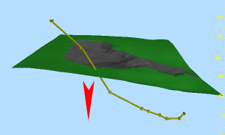
The following image represents the original positions of string vertices:
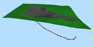
If projected using the Point
option, only those points that can intercept the selected surface(s)
or section(s) from their original position, in the specified direction
will be 'dropped' onto the surface, resulting in the following:
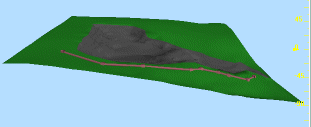
If, however, the Infinity
option is used, all points will be dropped onto the selected surface(s)
or section(s) from an infinite distance, resulting in the following:
Project To: select
which wireframe surface(s) and/or section(s) you wish to use as projection
surfaces for controlling the projection operation. Note that surfaces
do not have to be visible to be selectable, and single or multiple
surface or section objects (or combinations of data types) can be
selected.

