|
|
Choosing appropriate settings in the dialog |
Wireframe Verify
To access this dialog:
-
Activate the Solids ribbon and select Operations | Verify
Triangulates the chosen wireframe and tries to produce consistent normals. If there are shared edges, the normals generated may not be correct.
The primary purpose of the Verify function is to create manifold surfaces from the wireframe. In order to do this, Verify will look for the highest, non-vertical triangle in the selection, and alters its normal so that it is pointing ‘upwards’. It then looks at all adjacent triangles, and ensures that their normals are consistent with that face. The process then continues from these faces, until no more are unassigned, or adjacent triangles are found. If all triangles have been assigned, the process is complete, otherwise the SurfaceNumber is incremented, and the process starts again with the highest, non-assigned, non-vertical triangle.
Problems can occur when more than 2 triangles share a common edge (reported as Shared Edges). An edge is regarded as being shared when more than 2 triangles share the same vertex pair. Triangles which have different vertices, even if they are in the same location, are not considered to be adjoining, and will not contribute to a shared edge. This can be a useful way of separating multiple wireframes in the same object, and prevent shared edges. However, the Remove Duplicate Vertices option will collapse all filtered vertices sharing the same point in space, or within a specified tolerance, to a single vertex, so this option should be used with care where duplicate vertices have been intentionally used to separate surfaces. When a shared edge is encountered during surface generation, the first pair of triangles found to share that particular edge are regarded as being adjacent, while the third triangle found is not, and tags the edge as being shared. If, however, a fourth triangle is found to use the edge, it is paired with the third triangle, and the edge is no longer tagged as being shared. The process continues for odd and even numbers, and will always attempt to pair up triangles, unless the Stop at Shared Edges has been selected.
Where different surfaces are independent and should be verified separately to each other, the Key Field option can be used to group together parts of the wireframe containing the same values in the Key Field column. Triangle vertices from different Key Field groups will never be regarded as being duplicates, and triangles from different Key Field groups will not be regarded as sharing edges (see "Multiple Surface Verification", below).
If Stop at Shared Edges has been selected, no triangle sharing an edge with more than one other triangle is regarded as being connected across that edge, and edge triangle tags the edge as being a shared edge.
The Verify dialog features a wealth of options for the validation of wireframe data. In addition to the contextual information listed below you can also view a series of examples here.
A Key Field option exists within the Wireframe Verify dialog to allow you to define a specific data field that will denote separate data entities within the same object. If this is left as <none> (the default), the behaviour will be that all duplicate vertices and faces will be reported even if they belong to abutting wireframe surfaces (where you would expect more than one vertex to occupy the same location).
Specifying a keyfield, however, determines that wireframe elements with different values of the keyfield are kept separate. This can also be thought of as running multiple verify operations - with each run filtering the wireframe with a different unique value of the keyfield.
When a keyfield has been specified, vertices will not be regarded as being duplicates if their keyfield values differ from each other (even if they are in the same spot). Similarly, overlapping triangles will not be treated as duplicates if their keyfield values differ. Finally, when performing the adjacency calculations (which are used for calculations of normals, as well as checking for open and shared edges), no triangles with differing keyfield values will ever be connected together.
This makes verifying complicated wireframes which may consist of multiple touching wireframes simple.
|
|
Wireframe verification can only be applied to entire wireframe data objects - it is not possible to verify a subset of a wireframe object. |
For further advice and guidelines on using this command, please refer to Wireframe Verify Examples.
Field Details:
Name: displays the name of the wireframe object to be verified.
Key Field:
define a specific data field that will denote separate data entities
within the same object. If this is left as <none> (the default),
the behaviour will be that all duplicate vertices and faces will be
reported even if they belong to abutting wireframe surfaces (where
you would expect more than one vertex to occupy the same location).
Specifying a keyfield, however, determines that wireframe elements
with different values of the keyfield are kept separate. This can
also be thought of as running multiple verify operations - with each
run filtering the wireframe with a different unique value of the keyfield.
When a keyfield has been specified, vertices will not be regarded as
being duplicates if their keyfield values differ from each other (even
if they are in the same spot). Similarly, overlapping triangles will
not be treated as duplicates if their keyfield values differ. Finally,
when performing the adjacency calculations (which are used for calculations
of normals, as well as checking for open and shared edges), no triangles
with differing keyfield values will ever be connected together.
This makes verifying complicated wireframes which may consist of multiple
touching wireframes simple.
Store surface number: this drop-down list identifies
separated surfaces based on face connectivity, assigns a separate
index to each surface, then stores that index in the field specified.
Note that a SURFACE field is entirely optional; it isn't required
for any Studio process.
Stop
surface at shared edges:
one of the key problems faced by any CAD packaged dealing with meshes
is how to deal with a situation where one wireframe triangle has at
least one shared 'edge' with another neighboring triangle.
If Stop at Shared Edges has
been selected, no triangle sharing an edge with more than one other
triangle is regarded as being connected across that edge, and the
edge is tagged as being a shared edge.
Remove duplicate vertices: removes multiple instances of vertices which occur in the same location, and combines them into a single reference.
The Tolerance value is used to determine what a 'duplicate' vertex is; any vertices with a distance between them equal to or less than the value will be classed as being duplicates. In the event that this then causes a face to be degenerate (i.e. not having at least 3 unique coordinates), it will be classed as an empty face and reported or removed depending on the appropriate setting. Tolerance values are saved to the registry, so will be 'remembered' next time this dialog is used.
Any filtered-in vertices within the given Tolerance distance of another will
be removed, and any faces in the object which referenced that vertex
will now reference the first vertex instead. If duplicate vertices
are being intentionally used to mark breaks between adjoining surfaces,
then this function should be used with care, and it may be prudent
to call the Verify function multiple times, using filters to select
each sub-group in turn.
Remove empty
faces: removes any faces which have zero surface area; after
any duplicate vertices have been removed, empty faces can be detected
and removed. An empty face is regarded as being one where 2 or more
vertices share the same location in space. Empty faces will not be
used within the adjacency calculations or surface generation even
if they have not been deleted.
Remove duplicate faces: After any duplicate vertices (see above) have been removed, duplicate faces may be detected and removed.
A face is regarded as being a duplicate of another face if it shares the same vertices. If duplicate vertices are present, faces will only be regarded as being duplicate if they share the same vertices, not if they have different vertices which lie in the same locations.
Duplicate faces may occur for a number of reasons.
In the case of strings being linked multiple times by mistake, only
a single instance of each triangle is required, and when the “Leave
Original” option has been selected, one of each set of duplicate triangles
will remain. Sometimes, the duplicate faces may be indicative of a
redundant internal surface caused by user errors during linking. In
these case, removing the Leave Original
option would remove all the triangles, and clear out the unwanted
surface.
Check for open edges: searches for edges which are not shared between 2 faces. Where found, a new object is created containing strings made up from the open edges.
Any
triangle which is not regarded as being connected to another triangle
is regarded as having an open edge. The strings generated from these
can useful for end-linking to ‘heal’ an object which is supposed to
be a closed volume, or for outlining the boundary of a Digital Terrain
Model, for example. Note that abutting triangles may be regarded as
having open edges if a) one of the triangles has been filtered out
for this operation or b) the triangles are using duplicated vertices
to indicate a required break in surface.
Check for shared edges: checks for edges shared by more than 2 faces. If found a new object is created containing strings made up from the shared edges.
A shared edge is marked as such if more than two
triangles use the same vertex pair, and Stop
surface at shared edges has been selected. If the Stop
surface at shared edges option has not been selected, an edge
will only be flagged as being shared if an odd number of triangles
are sharing it.
Check for crossovers: checks for faces that intersect, but are not adjoining. Where found, a new object is created containing strings made up from the edges formed by the intersections.
Where
non-adjoining triangles touch other is regarded as an intersection
or crossover. If this can be described as a line of intersection,
the resultant line contributes to the results string. In some cases,
however, the intersection may be coplanar, and no clear line of intersection
can be calculated. This will still be counted in the verification
report, but will not be added to the results string.
Check for feature edges: where this option has been requested, any adjoining triangles whose normals differ by the specified Feature Angle will contribute to the feature edge strings objects. It should be noted that, unlike the other option in this section, feature edges rarely indicate a fault condition, instead, they can be used to capture key geospatial features, such as toes and crests, generated directly from the wireframe to a string object.

When run, a new strings object will be created
in memory. This can be located in the Loaded Data control bar, and
will be shown with a (Verified Feature Edges) suffix, e.g.:
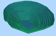
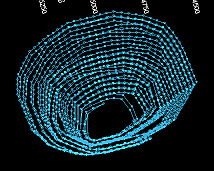
A quick way of checking the output results is to disable any wireframe data overlays and draw the string object alone, e.g.:

String data will only exist in memory at this
point - to create a physical file, the project (or individual object)
will need to be saved.
Write normals to data table: if selected, any subsequent wireframe verification will add a column to the wireframe data table in memory representing the normal direction of each wireframe vertex. Note that this is a 'one time' operation, i.e. if subsequent changes are made to the wireframe geometry (such as through a rotation command, for example) another verification process must be run to update the normal data values which may have become incorrect.
Face normals are normally stored within the geometry database, rather than the data table. However in some case it may be desirable to have references in the data table for subsequent calculations or filtering operations. Selecting this option will write NORMAL-X, NORMAL-Y and NORMAL-Z columns into the data table, and populate them. Please note that these values will only be correct at the time that the Verify process is run, as subsequent operations may change the geometry of the wireframe without updating these fields.
Write adjacency to data table: the creation ofopenedge andsharededge strings can be useful to indicate a problem in a wireframe and its general location, but it can be hard with more complicated wireframes to track the fault down further.
If this option is selected, TRIANGLE, TRE1ADJ, TRE2ADJ and TRE3ADJ fields will be used or created to store adjacency information for all filtered-in faces. The TRIANGLE number will be a one-based index of the face, unless filtering is present. In the case of filtering, the TRIANGLE number will start from one more than the highest TRIANGLE number used by the filtered-out faces.
The various TREnADJ
values will have the TRIANGLE
number of the face which is adjacent on that edge, or zero if no face
is regarded as being adjacent. Negative numbers indicate that an edge
is shared, and will be the
negative index of the first face found to use the edge. After the
verify, the use of appropriate filters can be used to find out which
faces are contributing to various fault conditions.
Write crossovers to data table: it can often be difficult to ascertain the cause of crossovers using the crossover string alone, especially in the case of coplanar intersections which do not contribute to the string.
This option will use or create a CROSSOVR column to store a crossover index for each intersecting face pair. For non-filtered objects, the CROSSOVR value will be a 1-based index. In the case of filtering, the CROSSOVR number will start from one more than the highest CROSSOVR number used by the filtered-out faces. Intersecting pairs of faces will use the same CROSSOVR numbers, but it may that additional intersections overwrite one or more of the faces’ data, so it should not be expected to see clean pairing of data in the results for anything other than trivial intersections.
|
|
Related Topics |
|
|


