|
|
Format Display Dialog The Format Display dialog |
Format Display
To access this dialog:
-
In the Format Display dialog, select the Overlays option and pick or create an overlay.
The Format Display dialog's Overlays tab is used to manage overlays and formatting templates and define their associated formatting parameters.
The tab has 3 main areas, select an item for more information:
-
Overlay Objects: add, edit, delete and select object overlays and formatting templates.
-
Overlay Format: define groups of formatting parameters for the selected overlay or template.
-
Template: update template parameters; apply templates to overlays.
Overlay Objects
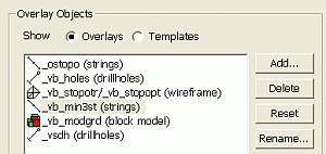
The Overlay Objects group is used to list, add, edit, delete and select object overlays and formatting templates.

Field Details
-
Show Overlays: Select this option to display a list of the current object overlays for the selected window (default).
-
Show Templates: Selecting this option to display a list of the available format templates. By default, this will include a base template for each data type (wireframes, points, strings, block models, drillholes) and any user defined or imported templates. When this option is selected, the Template group is hidden.
|
|
The selection of one of the above Show options determines whether this tab is in Overlay or Template editing mode. This may change the behaviour of other controls on this tab. |
More templates can be added, and any template can be edited, when in template editing mode. for more information on using the Format Display dialog to create and edit display templates, see Data Display Templates. In template editing mode, templates can be created, edited, deleted, reset to default, exported to a separate file or imported.
-
Overlay/Template Name: this pane lists the current object overlays or available project format templates; select an item in order to display (and potentially edit) the item's formatting parameters in the associated tabs in the Overlay Format group.
|
|
When the checkbox adjacent to a template is ticked, the template will be used to automatically create an overlay, applying the overlays parameters, each time an object of that type is loaded. More than one template can be selected for a data type. |
-
Add: depending on the selected Show option above, this button will:
-
-
add an overlay using the displays the Add Overlay dialog or,
-
add a template for a particular data type, using the Add Template dialog.
-
|
|
More than one overlay can be created for the same loaded data object. |
-
Delete: remove the selected overlay or template.
|
|
Deleting an overlay or template does not delete or unload any current object data. |
-
Reset: reset the selected overlay or template to the default display format settings for an object of that type.
-
Rename: rename the selected overlay, with a custom description, using the Rename Overlay dialog.
-
Import (template editing mode only): import an overlay Template file (.tpl), using the Import Templates dialog.
-
Export (template editing mode only): save the selected template to an Overlay Template file (.tpl).
Overlay Format
The Overlay Format group of tabs are used to specify the formatting parameters for the selected overlay or template.

The Overlay Format group may contain one or more of the following tabs:
Template
The Template group is used to apply the selected template to the selected overlay or, to update the selected template's formatting parameters.
|
|
This group is only displayed when the Show Overlays option is selected in the Overlay Objects group. |

Field Details
Template:
-
Template Name: select an overlay template from the dropdown, either for application or updating purposes.
-
Apply Template: apply the selected Template Name to the currently selected Overlay Name.
-
Update Template: update the selected Template Name with the formatting parameters currently applied to the selected Overlay Name.
-
Apply to all overlays displayingobject_name: select this option to apply the selected Template Name to all overlays containing the object object_name. This option will reformat all relevant overlays.
|
|
You do not have to re-create display formats each time a new data file is loaded, or a new overlay is created; instead, you can utilize the Overlay Templatesfacility to devise the optimum display format for a particular data type, and apply it to all objects as required. For more information on this, seeData Display Templates. |
Depending upon the object type of the selected data item, the available display styles will be enabled or disabled as appropriate. In addition, the availability of tabs will be affected by the drawing method selected. For example, if a Points drawing method is selected, all tabs will be visible, however, if you elect to display a selected object as Faces, you will not see the Symbols tab as these commands are not relevant to a face-visible object.

Data Display Templates allow you separate style and content in your Studio3 projects; a template contains all the data display instructions (simple or complex), and can be stored either in memory for use within the current project, or can be transferred to an external file for use in another project (although there are implications for this approach, which is discussed below).
Data display templates can be used to:
-
apply the same display format to multiple objects in memory (subject to limitations, see below)
-
apply the same display format to objects in different projects (subject to limitations)
-
automatically create an overlay or overlays each time data of a particular type is loaded into memory
Data display templates are saved with the current project file, so will be available the next time a project file is loaded. You can also elect to save template information to an external template (.tpl) file for subsequent import into any project.
For more information on Data Display Templates - see Data Display Format Overview.
Formatting Drillhole Overlays
The distinction between static and dynamic drillholes is important when applying overlay formatting; in-memory dynamic drillhole data will be listed as "Holes Overlay" in the Format Display overlays list, and can be formatted in the same way as a static (file-based) drillhole object. When a drillhole overlay (static or dynamic) is highlighted, the area on the right of the Format Display dialog will update to show a Style and Drillholes sub-tab.
Resolving Ambiguities when displaying block model intersections
Where the intersection of a block model and a plane is being displayed, an ambiguity can occur when the plane falls exactly on a cell boundary. This is caused by the fact that the two adjacent cells will intersect the plane at the same point, so it is not clear which should be used to dictate drawing attributes. To resolve this ambiguity, EwLib detects the case where a plane falls on a major cell boundary, and then offsets the plane by a small amount so that it falls into either one cell, or the other.
To control how this issue is handled, the Model Intersection Plane Bias option exists in theFormat Displaydialog - on theoverlaystab, which allows control over whether the intersection plane is biased forwards (in the direction of the plane normal), or backwards. The offset amount is preset at 1E-6 in block coordinates (i.e 1E-6*block width/height/length, as appropriate). In addition to the application option, individual overlays can override the default option with overlay-specific preferences.
What is an Overlay?
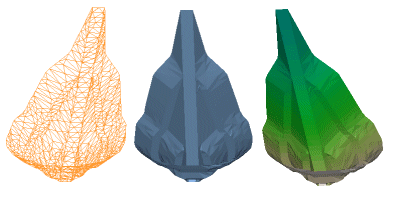
An overlay represents a single view of an object in memory; this can be loaded data or data created in Studio3. One file (object) can have multiple overlays, meaning that you can view the same object, in different ways, on screen simultaneously if required. This can be useful if you wish to create a label overlay, and draw the underlying vector data to the screen at the same time - in this situation you need two overlays for the same object: one for the vector data, and one for the labels, ensuring both are visible (using theStyletab).

|
|
Related Topics |
|
|
Formatting
Object Overlays The Format Display dialog The Overlay Type dialog |

