|
|
An explanation of fields and properties |

Update DTM
To access this dialog:
-
Solids ribbon | Operations | DTMs | Update DTM
-
Run the wireframe-surface-merge command from the command line
-
Use the quick key 'udt'
Also known as the "Update Hull" facility, this dialog allows you to perform a surface operation to update one wireframe DTM surface (or partial surface) with another.
In brief, this function will generate a new surface using the second wireframe data to update the surface elevation in preference to the first. The resultant surface area is the union of the first and the second wireframe surface, so there is no restriction that the second surface be bounded by the first.
The operation of the command can be likened to using a cookie cutter at the boundary of the second surface to cut out the first surface, and inserting the second surface into the first. Where there is a gap at the interface between the first and second surface, the gap is closed off with triangles, modelling the cut and fill relationship between the two surfaces.
Provided the second surface is bounded by the first the cut and fill wireframe solids can be generated by projecting the two surfaces with the wireframe-surface-project command to an elevation beyond the range of the two surfaces, and then completing wireframe- difference and wireframe-intersection operations on these surface solids as follows:
-
project the first surface data down to the lower elevation (A)
-
project the second surface data down to the lower elevation (B)
-
project the second surface data up to the upper elevation (C)
-
create the fill wireframe as the difference B minus A
-
create the cut volume as the intersection of C and A
If the surface bounded by one or more closed strings is required, this can be found by the following sequence of operations:
-
project the strings up and down to elevations beyond the range of the surface
-
link the upper and lower strings into a single wireframe group
-
intersect the original surface with the string surface(s) using the wireframe-merge command
-
delete the string wireframe surfaces, and the components of the original surface within or outside the strings as required.
If instead of the complete result of the wireframe-surface-merge command it was sufficient to replace the first surface with the second in the region of overlap then the wireframe-verify command could be used to generate the boundary string at the limit of the second surface, and then the previous command sequence could be used to do the cookie cutter operation on the first surface before adding the second. The surfaces are not guaranteed to be coincident on the boundary with this method.
Additional controls are available to manage how the source DTM is modified with respect to whether it is 'dug out' or 'raised' according to the interaction of the two surfaces. These options are explained in detail below.
Field Details:
DTM 1/2: select the first DTM data, either using the drop-down list to select a loaded wireframe object or using the Selected triangles option, and selecting data from one or more wireframe objects interactively using any 3D window. If using triangles, you will need to independently confirm your data selection for DTM 1 and DTM 2 using the corresponding Store current selection button.
Excavate DTM 1 with DTM 2: the elevation of DTM 1 will be set the minimum of its current elevation, or the elevation of DTM 2.
Elevate DTM 1 with DTM 2: the elevation of DTM 1 will be set to the maximum of its current elevation, or the elevation of DTM 2.
For both Excavate and Elevate options, if a jump between elevations on an open edge of object 2 would cause a break in the resultant surface, this gap is filled with vertical triangles.
The two options listed above are not exclusive, and if both are selected, the elevation of object1 will be the same as the elevation of object2 wherever they overlap in the XY plane. This is the default setting as it matches legacy behaviour for this function. See the image below for examples of each setting.
Example:
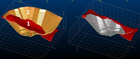
In the following example, a surface topography and pit DTM are loaded into memory. Object 1, in this case, is the pit and Object 2 is represented by the topography:
|
Options |
What Happens |
Result |
|
Excavate Option Selected Elevate Option Selected |
The elevation of the pit is set to be the same as the topography (object 2) wherever they overlap. The resulting DTM represents the overall boundaries of the pit, but with each point snapped to the topography. The attributes for the resulting object, in this case, are taken from the topography, as each point on the merged object is derived from that surface. |
|
|
Excavate Option Selected Elevate Option Disabled |
The elevation of the pit DTM is set the minimum elevation represented by both objects. In effect, the points of the pit wireframe are 'dropped' onto the nearest available surface, resulting in an object that matches the boundaries of the pit, but the minimum possible elevations. Note in the example how a mixture of both pit and topography values are used to represent the merged object, hence both attributes are shown. |
|
|
Excavate Option Disabled Elevate Option Selected |
As above, but maximum values for elevation are used when both objects are taken into account. Again, note how points for the new merged object are derived from both original DTMs, so both attributes are represented. |
|
Output: you can output data either within the Current object, an existing wireframe object (pick it from the list) or a new object (type a new name).
Copyright © Datamine Corporate Limited
JMN 20045_00_EN