|
|
Strings Properties Dialog - Labels Tab Labeling strings in VR |
Strings Properties Dialog - Labels Tab
To access this dialog:
-
In the Strings Properties dialog, select the Labels tab.
The Labels tab is used to control the formatting of the labels for strings in the active 3D window. Click Apply in this dialog to update the active 3D window with your changes.
|
|
The settings described here apply to the currently active 3D window and all linked external windows. Independent windows will be unaffected. |
A 'label' is represented by one or more text items. These can be freeform text, calculated values or values of point object attributes, or any combination. Labels are first defined by setting up the Text field with one or more text items (over one or multiple lines) and then defining that particular label's visual formatting.
You can define as many labels as you need, with each label supported by its own formatting settings. This means you could have, say, a large green label indicating the XYZ position of one aspect of your data on the left and a smaller label on the right of your data indicating another attribute value, e.g.:
In the above image, 2 separate labels have been defined for the same object overlay. You can quickly view all labels assigned to a particular overlay using the Label drop-down menu. This lists all labels in a table, letting you enable or disable particular labels as you need to, and even delete unwanted labels, e.g.:

You can add labels to the list (and format them independently afterwards) by clicking New.
If a label is disabled (using the check box in the labels list), it can still be selected, but you will be unable to edit any of its properties until it is enabled again.
Field details:
Display labels: if selected, then the controls on the Labels tab are activated, and any labels defined in this tab are displayed in the active 3D window when you click Apply
Column: this dropdown list allows you to select a column from the relevant data object.
|
|
You can select a virtual data column for labelling which will be recalculated dynamically during 3D object editing. |
Distance (string data only): display the distance along the string that the label appears. Often used in conjunction with the Intervals positional option.
DP: allows you to set the number of decimal places for the column shown in the Column dropdown list. The following options are provided:
-
-
Auto: values are displayed without trailing zeros; for example, '10.5000' is displayed as '10.5'.
-
From '0' to '6' decimal places: values are displayed using the number of decimal places that you specify.
-
Insert: adds the selected column into theText box using the criteria set in the Decimal places dropdown list.
Text: this group in the Labels tab allows you to create the labels that are shown in the active 3D window for the currently active label (the one shown in the Label field above). The content of the labels can either be typed directly into the Text box, or the accompanying buttons can be used. Labels can comprise static text, as well as values associated with the columns that you add.
Text can be entered directly, using the following convention:
-
Freeform text entry with no further formatting will be appear as typed
-
[Column name:.n] - adds values associated with the specified Column using n decimal places.
-
[Column name] - adds values associated with the specified Column.
|
|
When creating labels using the Column and Decimal places dropdown lists, you must click Insert to update the contents of the Text box. |
Font: this group allows you to set the style of font used by labels.
Type: specify either a 2D or 3D text style for labels.
-
-
2D: the size of labels remains constant, regardless of the viewing distance. If 2D is selected, then Plane cannot be selected in the Orientation group.
-
3D: the size of labels varies depending on the viewing distance, although when viewed at an excessively long distance, their display is turned off. If 3D is selected, then either Screen or Plane can be selected in the Orientation group.
-
Font: specify the font style using the accompanying dropdown list.
Size: specify the size of font using the spin buttons.
Alignment: allows you to justify multiple rows of text to the left, right or center.
Position:
allows you to label points or edges on strings, or the start, end
or center of each string. Groups of strings that have the same value
for a specified column can also be labeled.
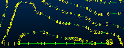
Every: choose to apply a label at every string vertex with [Point] or at the midway point of each edge using [Edge].
% along: add a label either at the [Start(0%)], [End(100%)], [Center(50%] or custom percentage along the string. The string direction is important here.
Intervals: adds a label at fixed intervals along the string. Define any value here you like, although values that exceed th length of the string will result in a single label being shown, at the start of the string.
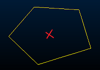
Centroid:
adds a label at the center of each string. The position of this label
for open and closed strings is shown below.
|
Type of String |
Position of 'Centre' Label |
|
|
|
Closed String
|
|
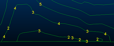
Group
by: only available if the Edges
option is set. If Group by is selected,
then a label is displayed by any groups of edges that have the same
consecutive value for the column specified in the accompanying dropdown
list. The label for each group of edges is positioned on the string,
at the centre of each group. This is demonstrated below.
|
Setting for Group by Option |
Result |
|
|
|
Selected
|
|
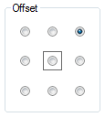
Offset: allows you to set the position of the label relative to each string. The string is represented by the central black box in the grid, and the position of the label is set by clicking the required button. For example, the setting shown below results in the label being positioned above, and to the right of the location specified in the Position group, in this case, the center of the string.
|
Offset Setting |
Position of Labels |
|
|
|
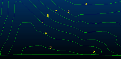
Orientation: this group allows you to set the orientation of labels relative to the strings. For 2D or 3D labels, their orientation can be set as Screen, Parallel or Perpendicular. For 3D labels, their orientation can also be set as Plane. The rotation of both 2D and 3D labels, and the requirement to keep them upright can also be specified, under the conditions described below.
Screen:
labels are shown in the plane of the screen, according to the rotation
angle. This option is available for both 2D and 3D labels. 3D labels
are shown in the following example.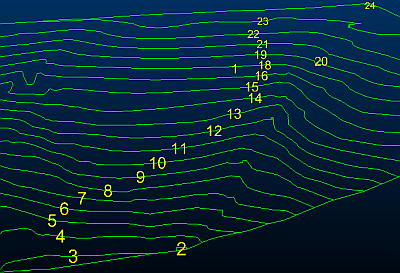
Parallel: labels are orientated in the direction of the string
or edge, as shown below.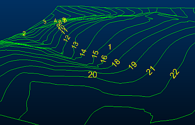
Perpendicular:
labels are orientated at right angles to the string or edge, as shown
below.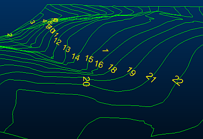
Plane: labels are orientated in the specified plane.
|
|
When the Plane option is selected, labels may appear back-to-front and/or upside-down, depending on the viewing angle. |
Azimuth
and Dip: if selected, then you can define the azimuth of the
labels within a range of -360 to 360 degrees, and the Dip
within a range of -90 to 90 degrees. In the following example, an
azimuth of '45' and a dip of '0' have been set.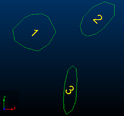
Section:
if selected, then labels are aligned to the section that you select
in the accompanying dropdown list. You can either select the active
section, or any currently-loaded section. An example is shown below.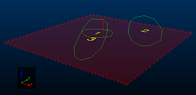
Best fit: labels are orientated in the best fit plane of each string, as shown below.
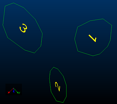
Rotation: if selected, then labels are rotated about their center, within a range of -360 to 360 degrees. This option is available for both 2D and 3D labels.
Keep upright: this option is available as follows:
-
-
2D labels: Parallel or Perpendicular must be selected in the Orientation group.
-
3D labels: Parallel, Perpendicular or Plane must be selected in the Orientation group.
-
|
|
|
Color: allows you to define the color of labels using a standard fixed color, or a display legend that references the attributes of the relevant data type.
Fixed: set this option to select a standard fixed color for all labels from the adjacent dropdown list. If the Legend option is selected, then the fixed color is also used to color labels that cannot be matched to a legend interval.
Legend: allows you to select a predefined, system standard or user-created legend. If data cannot be matched to a legend interval, then the associated label is colored using the color shown in the Fixed dropdown list.
Column dropdown list: after selecting a legend, use the dropdown list to select a data field containing color values to be matched to the legend.
As with all legend
dropdown lists, once a legend has been selected, it can then be displayed
or edited. A default legend can also be created automatically for
any selected field.
|
|
Show the currently-selected legend intervals and display properties. |
|
|
Edit the currently-selected legend using the Legends Manager dialog. |
|
|
Select a default legend for the selected data column if one already exists, or if no default legend is available, the Create New Legend wizard will appear to let you create a new legend. |
|
|
The color selected in the Fixed dropdown list is used to color labels whenever a value cannot be found for a selected legend and column. |
Options: this group provides the following options that allow you to improve the formatting of labels.
Always on top: set this option to prevent labels being obscured by the displayed data. This is particularly useful when labeling 3D data which may make it difficult to see labels due to their shape.
Group thousands: if labels contain long numbers, selecting this option makes them more readable by separating each group of three digits with a comma.
Hide absent values: if selected, then the '-' character, that is used to denote absent values, is hidden.
|
|
Related Topics |
|
|
String Properties Dialog - General TabString Properties Dialog - Lines TabString Properties Dialog - SymbolsTabAssociated files dialogInfo Mode List Dialog |


