Format Display: Symbols
Note: this topic relates to deprecated Design window functionality. The Design window is no longer available in Studio products.
To access this dialog:
-
With point or string data loaded and the Design window active, select the View ribbon and Format | Overlays followed by the Symbols tab.
-
Type 'fdd' in the Design window followed by the Symbols tab..
Symbols are used during data display to highlight the terminal points of string data. Symbols can either be specified carte blanche, meaning that the same symbol will be used throughout, or can be modified as regards size, rotation and/or shape according to a particular value in a database column.
Using this facility, it is possible, for example, to add a symbol representing the specific grade of mineral content at key positions along a drillhole sample, alternatively, they may simply be used to show the ends of line segments.
The Symbols tab is a sub-section of the Overlays tab, found within the Format Display dialog.
Field Details:
Symbol: the symbol used to define the terminal points of line segments can either be specified for all points, or a symbol value can be derived from a legend:
-
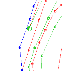
Fixed: display points as a selected symbol. The following image shows a non-default symbol used to distinguish line segment ends:

-
Column: If you wish to use a legend to define the symbol shape used, this drop-down list determines the column to be used to derive values for the display of symbols. For more information on creating legends, see Related Topics. If selected, the following option is available:
-
Legend: select a legend from the drop-down list. Note that the legend will contain the 'key' by which values derived from the 'column' will be matched against to assign a symbol type.
Size: symbols are 'truetype' in nature, meaning that they are scalable according to specified parameters. This section allows you to determine the size of a symbol throughout all points on a line, or according to a value derived from a database column associated with the selected line:
-
Fixed: specify a radius, in millimeters for all symbols on a line or;
-
Column: If you wish to use a legend to define the symbol size, and if the column to be selected contains numeric values, you can assign a column and legend for this purpose.
-
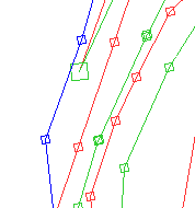
Legend: select a legend from the drop-down list. Note that the legend will contain the 'key' by which values derived from the 'column' will be matched against to assign a symbol type. The following image shows a symbol that has been sized according to the values in a selected string's database:

Rotation: you can specify the alignment of a symbol, either globally, or via legend values.
-
Fixed: specify a rotation in degrees for all symbols, or;
-
Column: If you wish to use a legend to define the symbol rotation, and if the column to be selected contains numeric values, you can assign a column and legend for this purpose.
-
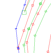
Legend: select a legend from the drop-down list. Note that the legend will contain the 'key' by which values derived from the 'column' will be matched against to assign a symbol type. The following image shows a symbol that is rotated according to the value in the Z_Position column for the selected string:

Dip: select a field from the drop-down list that includes dip values to be used when orienting symbols on a node-by-node basis.
Point Along Lines: select this check box to ensure all symbols are aligned with the direction of the selected line. If cleared, symbols will be displayed at the specified rotation regardless of the line direction.
Draw in 2D: selecting this check box forces symbols to be drawn in 2D and can be useful when symbols with a given dip and dip direction are no longer visible from the current view direction.
Apply to all overlays displaying...: if the currently selected object is represented by more than one overlay, you can elect to apply the current settings to all overlays for the specified object by enabling this check box. If cleared, the settings will apply to the currently selected overlay only. For more information on overlays, views, sheets and objects, see Related Topics.
Apply, OK, Cancel: as with most dialogs, you can elect to either make changes and apply them, keeping the dialog open or you can apply and close the dialog at the same time. Of course, you can also cancel the operation without applying changes. When applying changes, note that there will be a redraw of data, which may take several seconds, depending on the hardware involved and the size of the data sets in memory.
|
|
Related Topics |
|
|
Overlays,
views, sheets and objects Formatting Object Overlays |

