
Georeference Wireframe Map
To access this screen:
-
Georeference ribbon >> Georeference Wireframe.
-
Using the command line, enter "georeference-wireframe-map".
Important: Your Map window and 3D window have their own snap settings. Make sure you are able to digitize in both views before you start. For example, you can enable Always Snap in the map window and switch it off in the 3D view (say, because there are no landmark data to snap to in the 3D view). Doing this can help avoid the "no hit with active section" issue in the 3D view.
Georeference a loaded wireframe map by assigning world coordinates to known 3D surface landmark positions.
A table of 'local' and 'world' coordinates is created. If possible, the loaded wireframe map and all 3D contents (features, sketches, comments and so on) are 3D transformed to allow the map to be shown in world coordinates alongside (potentially) other geolocated reference data.
Once a wireframe map is georeferenced, it can be displayed or hidden in the 3D world view either by editing its visibility status in the Project Data control bar, or using the Georeference ribbon's Show Map in 3D Window toggle.
Tip: Once georeferencing is complete, both map and world windows show wireframe map data in the same (world) coordinate system, although the map window will show only the wireframe map and its associated field data, without other reference data potentially cluttering the view.
To georeference a wireframe map using known coordinates:
-
Load the wireframe map to be georeferenced.
-
Run the georeference-wireframe-map command.
-
Display the wireframe map view (not the 3D world window).
-
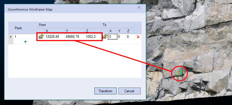
In the From column, either enter known coordinates explicitly for XYZ of a landmark surface position (say, a bolt or face mark).
-
Alternatively, use the pick button and left-click or tap a position on the textured 3D surface. This automatically enters the nearest 3D surface position in the table.
Once all 3D coordinates are entered, a numeric indicator appears on the surface in the position selected or specified, for example (red circle shown for clarity only):
-
-
Display the 3D world view.
-
In the same table row, but in the To column, either enter the known XYZ world coordinate position of the landmark point, or use the pick button to select a position in the 3D window.
Note: Right-click snapping is supported here, or if you are using a stylus, you can enable Auto Snap and snap to reference data that way.
-
Add as many or as few landmark positions as required. In each case, a green (local) and red (world) indicator is added to the view:
-
If only a single point (current and target) is specified, a simple data translation occurs, that is, without rotation around any axis.
-
If two point pairs are defined, a translation is applied using the first point pair, followed by azimuth and dip adjustment to align the second point target.
-
If three point pairs are defined, the same transformation as for two points is applied, with a subsequent roll adjustment to honour the third target position.
-
If more than three point pairs are defined, a 'best fit' transformation is applied to adjust the data position and orientation as closely as possible to all target point locations.
-
-
Click Georeference to relocate your selected object(s).
The transformed wireframe map becomes visible in the 3D window, aligned (as closely as possible) to the coordinates specified.
To georeference a map without supplying coordinates:
You may just want to display your wireframe map in 3D without georeferencing (showing the map centre at 0,0,0).
-
Load the wireframe map to be georeferenced.
-
Run the georeference-wireframe-map command.
-
Display the wireframe map view (not the 3D world window).
-
Check Don't apply transform to coordinates.
-
Click Georeference.
-
Display the 3D window.
Your map appears centred at 0, 0, 0.
Related topics and activities