Strings Properties Dialog - Symbols Tab

Adding symbols to strings

Strings Properties Dialog - Symbols Tab

To access this dialog:

  1. In the Strings folder in the Sheets Control Bar (active 3D window Sub-Folder), right-click a strings file and select Properties.

  2. In the Strings Properties dialog, select the Symbols tab.

The Symbols tab allows you to add 2D or 3D symbols to each string vertex, and configure their size, rotation and color. The following fields are available.

note.gif (1017 bytes)

The settings described here apply to the currently active 3D window and all linked external windows. Independent windows will be unaffected.


Field Details:

Display symbols: if selected, then the controls on the Symbols tab are activated, and any symbols that you specify are shown in the 3D window.

Symbol: this drop-down list contains a reference to each symbol that has been defined for the selected string object overlay. Groups of symbols can be managed using New and Delete.

By default, a [Symbols] group will be selected, and cannot be deleted. Adding a new symbols group will add an incremental suffix to the latest Symbol entry, e.g. Symbols_1, Symbols_2 etc.

All other formatting options on this screen relate to the currently selected symbol group. So, for example, you want a string to have a green circle symbol at each vertex position, but a blue diamond at the center position of each edge, pointing along the line like this:
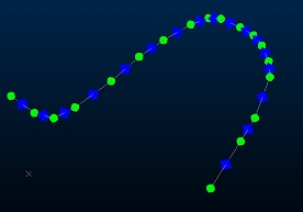
To achieve this, you can:

  1. Enable the Display symbols check box.

  2. With the default [Symbols] group selected, ensure the Style is Fixed to a fill circle, i.e.:

  3. Select the Color check box and pick a Fixed green colour:

  4. Set the 2D symbol to the desired Scale.

  5. Click New to create a new symbol group. It will be automatically named [Symbols_1]

  6. Choose a Fixed diamond symbol shape.

  7. Change the Color to blue

  8. Set the desired Scale.

  9. Select the Rotation | Point along lines option.

  10. Click Apply or OK.

You can add as many symbol groups to a line as you like.

Type: specify either 2D or 3D symbols. The contents of the Style group is updated, depending on your choice.

2D: a two-dimensional (flat) symbol that may have a 3-dimentional presence in space.

3D: a three-dimensional symbol. Either a Default box, or Imported model (DirectX) can be specified.

Style: allows you to specify the style of symbols.

If 2D is selected in the Type group, then the following options are shown.

Fixed: allows you to select a 2D symbol from the adjacent dropdown list. Different collections of symbols are shown by selecting them from the dropdown highlighted below.

Legend: if selected, then the style of symbols can be specified by selecting a legend from the adjacent dropdown list. The column that you select in the Column dropdown list is then matched to the legend, and the associated symbols are assigned.

Column: allows you to specify the column in the strings file that contains values relating to symbols. All columns in the relevant strings file are listed.

Show the currently-selected legend intervals and display properties.

Edit the currently-selected legend using the Legends Manager dialog.

Select a default legend for the selected data column if one already exists, or if no default legend is available, the Create New Legend wizard will appear to let you create a new legend.


If 3D is selected in the Type group, then the following options are shown.

Default box: if selected, then symbols are derived from a three-dimensional cube.

Imported model: allows you to create 3D symbols using a specified model. Select a DirectX model by clicking the adjacent Browse button.

Transparent textures: if selected, then color-keying is used to display a single color (black (0,0,0)) as transparent.

Size: the Size, Constraints and Scale groups are used together to define the effective size of symbols.

 note.gif (1017 bytes)

The 'size' of a symbol refers to its longest dimension. They can be defined in terms of screen pixels, by selecting Screen in the Scale group (2D symbols only). This setting provides a fixed, 'on-screen' size. Symbols can also be defined in world coordinates by selecting World. This setting allows their size to be specified in the virtual world, and results in their size varying according to their position in 'world-space'.


The Size group allows you to specify a base value for the size of symbols using the data attributes provided by a legend and column, or just a column. If neither a legend or column is specified, then all symbols are assigned a value of '1'.

Legend: select a legend from the dropdown list, or select <none>.

    • If a legend is selected, and Color by edge is selected in the Lines tab of the Strings Properties dialog, then the legend is used to define the size of symbols using the data attributes of the points associated with the selected column.

    • If a legend is selected, and Color by edge is not selected in the Lines tab of the Strings Properties dialog, then the legend is used to define the size of symbols using the data attributes of the strings associated with the selected column.

Column: select a column from the dropdown list that contains numeric data attributes for the size of symbols, or select <none>. All columns in the relevant strings file are listed.

    • If a legend and column are selected, then the legend defines the size of the symbols using the data attributes in the points file, for the selected column.

    • If a legend is not selected, then the size of the symbols is defined by the values in the strings file, for the selected column.

 note.gif (1017 bytes)

A filter legend can be used to define the size of symbols without the requirement to select a column.


Constraints: constraints can optionally be set for the base value by specifying a minimum and maximum size.The constrained values are then multiplied by the value in theScalebox to produce the final size.

Minimum: the minimum allowable size for symbols. A symbol with a base value below this value is treated as '0', and is not displayed.

Maximum: if selected, then any base values that are larger than the value set in the adjacent box are reduced to this size. The final size of the symbols is then produced by multiplying this value by the value in theScalebox.

Scale: allows you to optionally set a scale factor, and specify whether the size of symbols refers to their size 'on-screen' or in 'world-space'.

Scale box: the base size value is multiplied by this value to produce the final size of the symbols, taking account of any specified constraints. Any value greater than or equal to '0' can be entered.

Screen:if selected, thenthe final size of the symbols is their size on-screen. For example, symbols with a base value of '1', and aScalevalue of '100' are displayed on-screen at a fixed size of 100 pixels. Not available for 3D symbols.

World: if selected, thenthe final size of symbols varies according to their position in 'world-space' (if you zoom out, the size of the symbols decreases).

note.gif (1017 bytes)                                            

Specify the size of symbols as follows:

  1. Create a base value by setting one of the following options in theSizegroup:

  1. Neither legend or column: the base value is assumed to be '1'.

  2. Legend only: only allowed for filter legends. The size value of the relevant item in the legend defines the base value.

  3. Column only: the base value is the numeric data attribute in the specified column for the relevant symbol.

  4. Legend and Column: the base value is the size value of the relevant item in the legend. This is referenced using the data attribute of the symbol, for the specified column.

  1. Optionally specify minimum and maximum constraints in the Constraints group.

  2. Optionally specify a scale factor In the Scale group. Size values are multiplied by the scale value to produce the final size, which takes account of any specified constraints.


Size adjustments: allows you to specifically adjust the size of the symbol at the first vertex of a string, and/or the symbols associated with selected stings in the 3D window.

First symbol: allows you to set a unique size for the symbol at the first vertex of the string. The 'first' vertex is determined by the direction of the string.

    • [No Adjustment]: no adjustment is made to the size of the first symbol.

    • [Set]: define a specific symbol size for the first symbol in the adjacent box. By default, the size is set to '2'.

    • [Scale]: the first symbol is made proportionally larger than remaining symbols by setting a value in the adjacent box. By default, it is scaled by a factor of '2'.

Selected strings: (not available in InTouch) allows you to set the size of symbols associated with just the strings selected in the VR window.

    • [No Adjustment]: no adjustment is made to the symbols associated with the selected strings.

    • [Set]: define a symbol size in the adjacent box. By default, the size is set to '2'.

    • [Scale]: the symbols associated with the selected strings are made proportionally larger by setting a value in the adjacent box. By default, they are scaled by a factor of '2'.

Position: allows you to set the position of symbols in relation to string landmark positions:

Every: with this option you can align your symbols (using whatever Rotation options are set - see below) to either the string [Point] positions or [Edge] positions (between points) .

% along:either choose a predefined option (Start, Center or End) or enter a custom value where "0" is the start of the line and "100" is the final point position.

Intervals: define the distance you require between points. If the string cannot accommodate a full interval at the end, the terminal symbol will be omitted.

Color: allows you to define the color of symbols using a standard fixed color, or a display legend that references the attributes of the relevant data type.

Fixed: set this option to select a fixed color for all symbols from the adjacent dropdown list. If the Legend option is selected, then the fixed color is also used to color symbols that cannot be matched to a legend interval.

note.gif (1017 bytes)

If Imported model is selected in the Style group, then setting the Fixed option results in the color in the model being used.


Legend: allows you to select a predefined, standard or user-created legend. If data cannot be matched to a legend interval, then the associated symbol is colored using the color shown in the Fixed dropdown list.

note.gif (1017 bytes)  

A filter legend can also be used to define the color of symbols without the requirement to select a column. If a filter legend is selected, then the column dropdown list is not available.

Filter legends use logical expressions to denote the various legend intervals. The difference between this and the other legend types is that a legend interval is explicitly defined (for example, “AU>=3 AND AU< 10”).


Column: after selecting a legend, use this dropdown list to select a data field containing color values to be matched to the legend.

As with all legend dropdown lists, once a legend has been selected, it can then be displayed or edited. A default legend can also be created automatically for any selected field.

Show the currently-selected legend intervals and display properties.

Edit the currently-selected legend using the Legends Manager dialog.

Select a default legend for the selected data column if one already exists, or if no default legend is available, the Create New Legend wizard will appear to let you create a new legend.


note.gif (1017 bytes)

The color selected in the Fixed dropdown list is used to color symbols whenever a value cannot be found for a selected legend and column.


Rotation: allows you to set the orientation of symbols.

Fixed: only available for  2D symbols.if selected, then a fixed, on-screen rotation can be specified for symbols between -360 and +360 degrees.

Dip:if selected, then theDip,Dip directionandRollfields are activated. These fields allow you to set the orientation of symbols, in world space, using specified columns in the relevant strings file. TheDraw in 2Dfield is also activated.

Dip: select a column from the strings file that contains a dip value. The convention for dip is positive-down (a positive dip indicates a downward slope along the dip direction.

Dip direction: select a column from the strings file that contains an azimuth value.

Roll: select a column from the strings file that contains values for rotation about the symbol's vertical axis.

Draw in 2D: only available for 2D symbols. If selected, then the symbols are displayed in the plane of the screen, but still orientated in the direction that you have specified. IfDipis selected and theDraw in 2D option is not selected, then only the [World] option is available in theScaledropdown list.

note.gif (1017 bytes)TheDraw in 2Dsetting can be helpful when symbols with a given dip and dip direction are difficult to see in the current view direction.


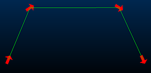
Point along lines: if selected, then the symbol is positioned on the vertex at the end of each string segment, and is aligned in the direction of the string, as shown below.

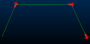
Point between lines: if selected, then the symbol is positioned on each point, and is orientated as follows:

    • At the ends of an open string, it is orientated in the direction of the string segment.

    • On the vertex between two string segments, it is oriented half way between them, as shown below.

  openbook.gif (910 bytes)  Related Topics


String Properties Dialog - General TabString Properties Dialog - Lines TabStrings Property Dialog - Labels TabAssociated files dialogInfo Mode List Dialog