|
Wireframe Properties Dialog - Lines Tab Controlling the display of a wireframe intersection in 3D. |
Wireframe Properties: Lines
To access this dialog:
-
In the Wireframes folder in the Sheets Control Bar (active 3D window Sub-Folder), right-click a wireframe file and choose the Intersection, Wireframe or Highlighted Edges display format (the Lines tab will not appear for other wireframe formatting options).
-
In the Wireframe Properties dialog, select the Lines tab.
The Lines tab is used to control how a wireframe data represented as a sectional intersection, wireframe line or highlighted edge is drawn to the screen in the active 3D window. The following fields are available.
These settings are particularly useful for formatting a wireframe
intersection view as it allows you to distinguish between multiple
wireframe objects displayed in section.
You can also use the Lines
tab to provide more complex formatting of, say, a wireframe displayed
with highlighted edges. In this situation, the wireframe itself can
be coloured based on the Color
setting on the General
tab, whilst the line aspect can be coloured using the color specified
on the Lines tab, for example:
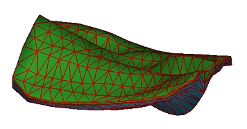
![]() |
The settings described here apply to the currently active 3D window and all linked external windows. Independent windows will be unaffected. Whilst offering similar functionality to the Lines panel in the String Properties dialog, these settings will only affect the target wireframe data intersection display. |
Field details:
Style: allows you to specify the style attributes associated with the wireframe line display. If required, a legend/column pair must be specified individually for both line style and width.
Fixed: select this option to specify a fixed line style for all lines in the object. Select the style from the adjacent dropdown list.
Legend: this is only available for wireframes displayed as an Intersection. Select a legend and column from the adjacent dropdown lists. This allows you to specify the line style for each edge or string in the object based on the values of an attribute within the wireframe's database.
Column: this is only available
for wireframes displayed as an Intersection.
Select a column from the dropdown list that contains the values to
be matched to the selected legend. As with all legend dropdown
lists, once a legend has been selected, it can then be displayed or
edited. A default legend can also be created automatically for any
selected field.
|
Show the currently-selected legend intervals and display properties. |
|
Edit the currently-selected legend using the Legends Manager dialog. |
|
Select a default legend for the selected data column if one already exists, or if no default legend is available, the Create New Legend wizard will appear to let you create a new legend. |
![]() |
The line style selected in the Fixed dropdown list is used whenever a value cannot be found for a selected legend and column. |
For objects loaded in the 3D view that contain the LSTYLE column, the default formatting in both the Style and Size groups is as follows:
- LSTYLE is selected in the Column dropdown list.
- Standard Datamine LSTYLE fields is selected in the Legend dropdown list.
If the LSTYLE column is not present, then a fixed, solid 2D line style with a width of one pixel is used by default.
Size: this and associated controls are only available for wireframes displayed as an Intersection. Intersection line data can be sized and scaled by either a fixed amount or based on data attribute values. The Scale of data represents the millimetre screen distance.
![]() |
The width of strings in a 3D window may be limited by your graphics hardware. You can find out more about this here. |
Legend: for the relevant strings and edges, specify a legend from the dropdown list that contains values for line width.
Column: select a column from the dropdown list that contains the numeric data attribute for line width.
Color: allows you to define the color of lines using a standard fixed color, or a display legend that references their associated data attributes.
Use
fixed color: set this option to select a standard fixed color
from the adjacent dropdown list for all lines in the object. If unselected,
a default colour will be used.
If enabled, the color setting will
used as an override, meaning it will be used instead of
coloring parameters set on the General tab for the line element of the target wireframe
overlay. For example, if you have displayed your data using the Wireframe display format and choose a Fixed blue colour on the General tab, but select the Use
fixed color option on the
Lines tab and choose red, the wireframe data will be drawn in red,
with the nominated line style and thickness.
However, you can use this setting in combination with the General tab
settings if both wireframe and line elements are displayed, as with
the Highlighted Edges formatting option. In this case, the General
tab will dictate the wireframe surface color(s) and, if enabled, the
Lines tab color will be used
to color the edges.
If an intersection is drawn, the General line colour will be used unless Use fixed color is enabled, in which case a different colour (and linestyle and size) can be set.
![]() |
Related Topics |
|
String Properties Dialog - General TabString Properties Dialog - SymbolsTabStrings Property Dialog - Labels TabAssociated files dialogInfo Mode List Dialog3D Window OpenGL Constraints |