|
|
DTS Dependencies Synchronizing dependencies between Studio OP and |
Your application lets you interactively specify the type of dependency between activities present in Datamine's Datamine Task Scheduler (DTS ) application.
This facility is also available in the DTS application. This procedure allows you to review your selections instantly in animated form, and to update the linked DTS schedule at the same time.
This dynamic link can save valuable time when visualizing the effect of your decision to, say, change a dependency from a start-start relationship to one where a percentage overlap is required in time, or if you need to introduce a specific delay between one or more activities.
This section describes the following procedures:
-
Generating a linked DTS schedule.
-
Setting dependencies in Studio OP, and synchronizing them with the currently connected DTS schedule document.

These procedures assume that the following conditions are met:
-
Sequenced wireframe data has been loaded into your application.
-
DTS is running.
-
The Sequence Control bar and DTS ribbon are displayed.
-
A connection to the active schedule in DTS has been made.
|
|
Clicking Refresh on the DTS ribbon in your application will make a connection to the active schedule in DTS |
Generating a linked DTS Schedule
-
In DTS, create a project file that includes the required attribute handling, convention, calendar and other configuration settings. Save this project file to disk in a known location.
Alternatively, skip to step 3) if an existing DTS project file exists, and you wish to update it. -
Configure your DTS schedule file output to include/exclude data/information relating to the current dependencies (press F1 in the application for more details).
-
Ensure DTS is running on the local system.
-
Rearrange your Studio application and DTS viewing windows so they are both visible.
-
In your application, activate the DTS ribbon.
-
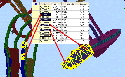
Enable the Select toggle. This will enable Data Selection mode, allowing you to click on a wireframe segment in the 3D window, whereupon the corresponding activity in DTS will be highlighted. Alternatively, select a record in DTS and the relevant wireframe segment will become highlighted.
You can select one or multiple segments/records by holding down the <CTRL> key.
|
|
Whilst in Data Selection mode, you must select the <Shift> key in order to perform other data selection and digitizing functions (e.g. creating a new string, spinning the view and so on.) |
Setting a Dependency Relationship between multiple object segments in Studio
-
Configure your view so that you can see all of the object segments for which you wish to define a dependency relationship (start-start, start-end etc.).
-
Using the DTS ribbon, click Refresh.
-
In DTS or the 3D window, select multiple concurrent data segments as follows:
-
Select the first segment.
-
Hold down the <CTRL> key and select the next segment.
-
To select further segments, hold down the <CTRL> key and select them in the correct order.
-
-
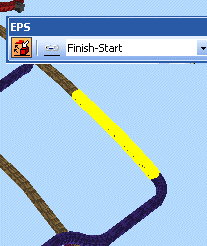
In the 3D view, confirm that they are highlighted. For example:

-
In the example above, the selected segments are linked by a Finish-Start relationship. Note that the description in the DTS ribbon is not linked to the data selection - it only shows the currently selected dependency type for future application.
-
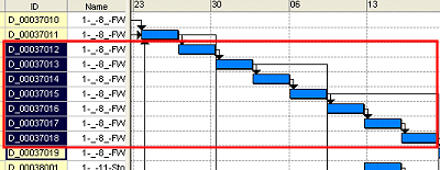
In DTS, review the Gantt chart corresponding to the selected segments. As you are connected to the schedule, they will automatically be highlighted, e.g.:

The dependency relationship (Finish-Start) is clearly shown.
-
Back in the 3D window, select an alternative Constraint using the DTS ribbon, e.g. select [Start-Start] (ok, in this case, where the strings are consequent drive segments, this wouldn't be realistic, but it proves a point graphically).
-
In the DTS ribbon, click Link
-
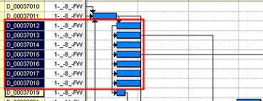
Have a look at your DTS Gantt chart; the activities are now linked according to the new relationship, for example;

It is not recommended to use a selection box to select multiple tasks as this results in the order of the tasks within the selection being undefined. -
To see the effect of your changes in a 3D view, click Refresh
This repopulates the default animation field (M4DANI) for your loaded data object, based on the contents of your DTS schedule (which now contains new dependency information).
-
Press Play on the Sequence Control toolbar to see the effect of your dependency edits. In the above example,all 7 drive segments will complete within the same animation frame (as they all start at the same time and are one frame in duration).
-
The following Constraint Types can be selected in the Constraint drop-down list on the ribbon:
-
Finish-Start - the successor task occurs when the predecessor task has been completed.
-
Finish-Finish - the predecessor task and the successor task are scheduled to complete at the same time.
-
Start-Start - the predecessor task starts at the same point in the schedule as the successor task.
-
Start-Finish - the successor task starts before the predecessor and finishes when the predecessor is scheduled to start.
-
Percent Overlap - the successor task lags the predecessor task by the percentage defined in the lag field.
-
A time delay can be specified in the DTS ribbon, in the Lag box.
The following units can be used:
-
"mi" – minutes, for example 1mi.
-
"h" – hours, for example 1h.
-
"d" – days, for example 1d.
-
"w" – weeks, for example 1w.
-
"mo" – months, for example 1mo.
-
"y" – years, for example 1y.
-
"%" - percentage of overlap, for example 20%. A value for "%" can only be specified if <Percent overlap> is selected in the Constraint Type drop-down list.
-
The layer can be specified in the DTS ribbon's Layer field.
|
|
You can achieve the same end result (synchronizing dependency types between DTS and the 3D window) by setting the relevant parameters in DTS (using the Outline Simple toolbar) and re-synchronizing the schedule in Studio using the Refresh button on the ribbon. |
Synchronizing Data between Studio UG and DTS
The Dependency Synchronization screen is used to align data between your product and Datamine Task Scheduler (DTS), and specifically, schedule dependency information. The following can happen as a result of this:
- You commit existing dependency information in your project to the DTS project.
- You add schedule dependencies to your project schedule from DTS where they didn't exist before.
You can also choose to ignore dependency differences between your product and DTS if you wish.
Legend Mismatches
When exporting data to DTS, it is important that material categories in DTS and legend categories in Studio UG are matched correctly, or this can lead to misclassification of materials. As such, the following logic is adopted when exporting data:
If there are legend categories in Studio UG that do not exist as material categories in DTS then they are added during the Schedule Update process.
If there are material categories in DTS that do not exist as legend categories in Studio UG then the export is prevented, and you are shown a message highlighting the problem material categories. These need to be resolved before an export is reattempted.
More about dependency synchronization...


