
MSO - Controls - Boundary Surface Method
To access this screen:
-
Using the MSO ribbon, define a surface boundary shape framework and and select Controls.
The Controls panel, part of the MSO workflow, is used to define the base geometries for stope shapes to be created.
This topic covers the stope shape generation controls relevent to the Boundary Surface method.
For narrow high grade reefs or lenses, where subcell modelling has some spatial accuracy limitations, it can prove more effective to model stope shapes off the geological wireframes directly. The stope walls are modelled as a mesh of points from 3x3 to 6x6 points. Dilution, orebody positioning in the stope, and an option to split the stope into waste and ore components, are provided.
Minimum and Maximum Stope Width Settings (Slice or Boundary Surface Methods)
This section is used to define both the minimum and maximum permissible stope width dimensions, plus the minimum pillar width between stopes.
You also need to decide how the stope width is being defined as either the Apparent Width, True Width on Section or True Width.
You can choose the True Width on Section option as a simpler variation on True Width. With True Width on Section, the true width is based on the stope dip angle on the framework section, and ignores changes in orebody strike when estimating the true width. Note that the pillar width parameter is defined as the distance in the horizontal plane i.e. the apparent pillar width.
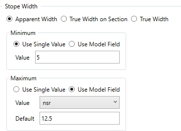
Regardless of the Stope Width method adopted, you can set a minimum and maximum mining width as either a fixed value or according to the value of a model field. If you are using model-based values, a default must be chosen to handle data absence in the model object.
In the image below, the Minimum mining width has been set to a constant value of 5 and the Maximum will be set based on the contents of the selected field, setting 12.5 if absent data is found:
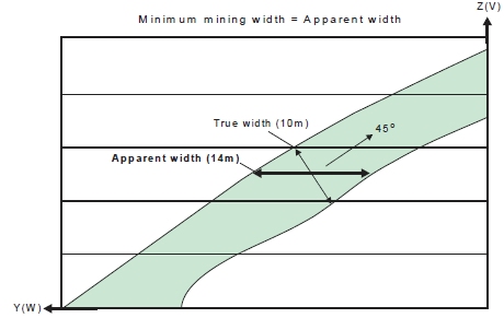
The Minimum mining width parameter is defined as distance in the horizontal plane on the framework section along the W-axis (and consequently measures the apparent width). If the orebody dip is moderate or the strike deviates from the framework axis, then it would be appropriate to make a correction to the width specified to better approximate the intended true width. As an example, if the minimum stope width in the true-width dip-direction was intended to be 10m and the orebody was dipping at 45 degrees, then setting the minimum stope width to 14.1m (horizontal distance) would approximate the intended minimum stope width. Note that the true width is a function of both strike and dip orientation in three dimensions for the general case.
-
If stope wall angle ranges are the same for both the hangingwall and footwall, or roof and floor, then the minimum stope width is checked at the stope corners.
-
If stope wall angle ranges are different, then the minimum stope width is checked at the wall centre, because the optimal seed-shape is measured at the wall centre, and the annealing shape must be measured in the same manner to ensure that a feasible annealing shape is available at the start of annealing.
The Maximum mining width parameter is defined as distance in the horizontal plane on the framework section along the W-axis (and consequently measures the apparent width).
An example use for the maximum stope width is to restrict the transverse dimension for geotechnical purposes (e.g. not to exceed the stable hydraulic radius for the crown face or the strike-face walls).
|
|
You can also use the Options panel to split the stope width into smaller intervals without pillars. The maximum stope width should be interpreted as maximum stope width between pillars. This "post-processing" approach is preferred over the now discouraged approach of specifying a small (non-zero) pillar width, and a maximum stope width equal to the interval sought, as was used in earlier versions of MSO |
You can also define a Minimum Pillar between Parallel Stopes, which will be applied to honour operational constraints such as equipment size and operability in restricted spaces. As with the Minimum and Maximum mining width controls, you can either choose a single constant value for the run or a model field containing one or more values (and, again, a default value must be set as well). A pillar will separate seed-shapes or stope-shapes if the maximum stope width would otherwise be exceeded, or low grade/waste can be isolated from stope shapes.
Waste cells (representing mineralization below cut-off, or rock without mineralization) surrounding the ore cells are required for runs with sub-stopes, as the location of the mined-out cells is used to force the pillar width between stopes and sub-stopes, and between sub-stopes and sub-stopes.
If the stope wall angle ranges are the same for both the hangingwall and footwall, or roof and floor, then the minimum pillar width is checked at each corner. If the stope wall angle ranges are different, then the minimum pillar width is checked at the wall centre.
Mesh (Boundary Surface Method)
Define the mesh of points to use when modelling stope shapes off geological wireframes. Set the number of points in the U and V directions, noting that higher numbers will exponentially increase processing time.
The boundary surface can be positioned between the stope walls at either the Centre, Near or Far wall, and the stopes can be output as a single shape or by splitting the ore and surrounding waste into separate shapes, as dictated by the Split at waste/ore boundary check box.
Stope Width: another critical element of your optimization settings, define minimum and maximum mining widths. See "Minimum and Maximum Stope Width Settings", above, for more information.
Stope Dilution: Dilution refers to material below cut-off grade that gets blended with ore, thus reducing the grade of excavated material.
if the Use Model Fields check box is selected, you can specify both a Near Dilution Field and a Far Dilution Field from the input model. Only numeric fields are available for selection.
Stope Dip/Strike Angles: set the Minimum and Maximum permissible angles for dip and strike. You can either calculate independent hangingwall / footwall angles for each stope or use a global near and far definitions across the stope portfolio.
For Stope Dip Angles, you can elect to force the same values for floor and roof or independently specify the angle range for each. Similarly, for Stope Strike Dip Angles, you can choose whether to use a universal setting for Floor Strike Dip Angle and Roof Strike Dip Angles or set them independently.
For both dip and strike angles you can also denote the Maximum
Change between concurrent angles in the specified stope sequence,
to avoid impractical step changes between stope geometries. This is
entered in degrees, with the default being 20 degrees.
Here's an example: in the left image (below), the Minimum Stope Strike Angle is -45 degrees, and the Maximum is +45 degrees, with a maximum permitted change between strings of 20 degrees. In the right image, the minimum is reduced to -25 degrees and the maximum is +25 degrees, with a step change of 10 degrees permitted:
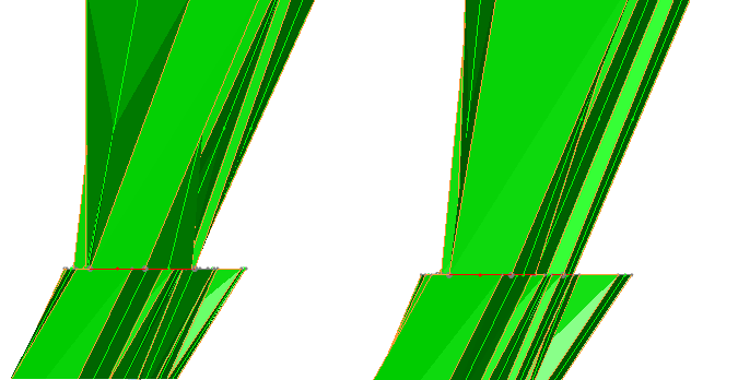
In this particular example, allowing a wider range of strike angle permits a more angular stope shape in order to meet the required objective. The scenario includes a more restricted angle range and change control, so whilst the shape is still optimal, it is optimal whilst honouring the new restrictions (which may be necessary to ensure a maximum angle threshold for a rock type is not breached.
Stope dip and strike angles can be defined explicitly, or can be picked from block model fields. Select the Use Model Fields (Stope Dip Angles) or Use Model Field (Stope Strike Angle) options, then pick a field from the optimization model. You can define a field containing dip or strike angle values representing the Minimum, Minimum Default (used where no minimum value is found, Maximum (plus associated default value), Maximum Change (plus associated default value).
More general information on angle conventions in MSO...
Related topics and activities: