
MSO - Structure Surfaces
The following controls are available to both Standard and Advanced Sliceframeworks, and the Boundary Surface framework.
A structure surface is a wireframe file that can be used to refine the boundary surface of a stope. In brief, the wireframe acts as a snapping surface providing the resulting shape is economically viable.
Use Structure Surface Wireframe:
select this option to select a Datamine wireframe triangle file. This
option is available for both Standard
and Advanced Frameworks.
This option results in the stope-shape either snapping-to the structure surface (e.g. include “waste” that would “normally” fall into the stope-void due to the presence of the structure) or standing-off (expanding) from the structure surface (e.g. leaving a skin of “ore” against the structure for dilution control i.e. ore loss).
MSO assesses both options in generating the seed-shape, and applies the same rules to the annealed shape. If the snapping-to shape is sub-economic, then MSO will still consider the “standing-off” option. This will depend upon the relative position of mineralized material and the structure surface.
Expand option:
You will need to define the range within which expanded stope points are created at the loaded surface. The default option is to set the maximum 'snap distance' from the floor and roof (Max Floor Distance and Max Roof Distance).
You can choose whether to specify a minimum distance from the structure wireframe, within which the stope expands the stope-shape to that structure surface. If one or more corners are within the minimum distance, the remaining corners are tested against the maximum distance. This is the Use Minimum Distances option, which if selected, will require you to set a Min Floor Distance and a Min Roof Distance.
The stope wall is snapped-to the structure position if it falls within the set criteria (minimum - target, maximum - range). This can result in a dip angle that is flatter or steeper than set in the stope geometry parameters.
Snap To option:
With this option, you set the distance range from either the floor or roof - you just select the wireframe file, and a Min Distance and Max Distance. Stope points that fall within this distance range from the loaded control surface will be 'snapped' to the surface.
Optimize: horizontal deposits, for example mineral sands where the mineralization is found under overlying waste, add additional complexities for generation of the optimal mining surface.
You can run the Stope Optimizer to find the optimal mineralized profile but not been possible to take into account the cost of removing the overlying waste where it can be mined separately, or the penalty applied when the whole profile is mined and processed as a single unit. Using the topography surface as a Structure surface, and snapping/expanding the optimized mineralized zone to the surface is a valid approach, but this option does not resolve the cost or penalty.
Instead, you can choose to optimize the horizontal mining unit that has been developed.
If Optimize is selected, you can choose a wireframe triangle/point file pair to specify a surface that will not be mined past. Typically, this surface is topography, but it doesn't need to be. You can also choose what surface represents using the Position drop-down list.
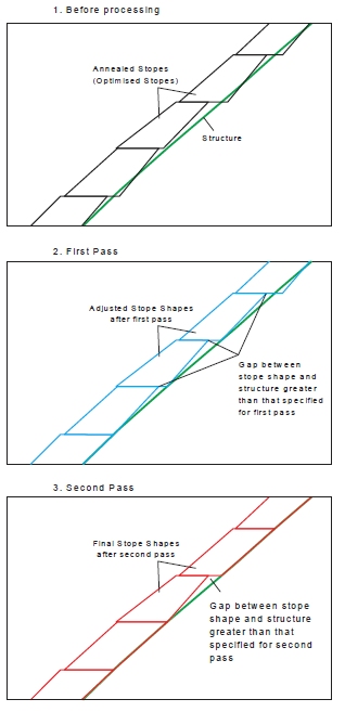
The following example shows how a Structure Surface Wireframe is used,
Related topics and activities: