
RECBLKST Process
To access this command:
- Reserves ribbon >> Reconcile >> Outlines Model.
- View the Find Command screen, select RECBLKST and click Run.
- Enter "RECBLKST" into the Command Line and press <ENTER>.
See this process in the Command Table.
Process Overview
Compare the tonnes and grades of model cells within
outlines between two surfaces. Subcell divisions are created in the input
block model by the process and written to the output model. The output
model can be used to view the volume within the outlines between the two
surfaces. Optionally an overall bounding perimeter can be supplied.
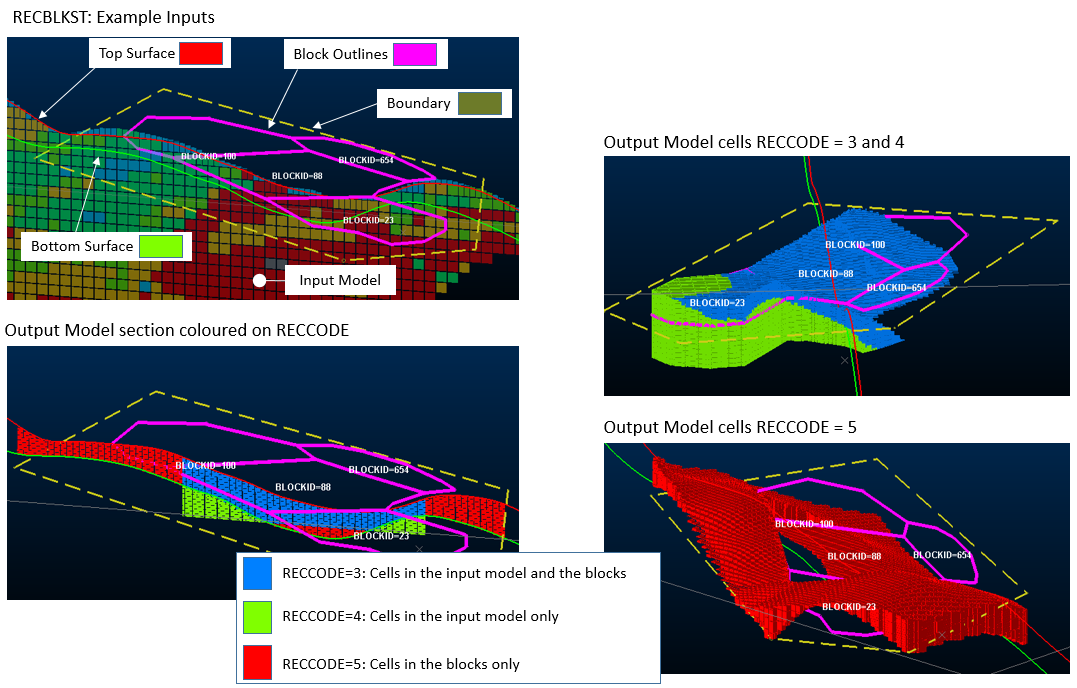
An example of the inputs and outputs of this process:
Input Files
|
Name |
Description |
I/O Status |
Required |
Type |
|
MODELIN |
Input model file for reconciliation. |
Input |
Yes |
Block model |
|
BLOCKS |
Input string file containing mining outlines. These are projected up and down to define designed volumes. Each string must have all its points on the same elevation. |
Input |
Yes |
String |
|
PREVTR |
The wireframe triangle file of the initial mining surface. |
Input |
Yes |
Wireframe triangle |
|
PREVPT |
The wireframe point file of the initial mining surface. |
Input |
Yes |
Wireframe points |
|
MINEDTR |
The wireframe triangle file of the second or mined surface. |
Input |
Yes |
Wireframe triangle |
|
MINEDPT |
The wireframe point file of the second or mined surface |
Input |
Yes |
Wireframe points |
|
PERIMIN |
If specified this optional file must contain at least one perimeter (e.g. a bounding pit perimeter) to control the area in which processing occurs. |
Input |
No |
String |
Output Files
|
Name |
I/O Status |
Required |
Type |
Description |
|
MODELOUT |
Output |
Yes |
Block Model |
Output reconciliation model. This contains subcells between the
first (designed) and second (mined) surface with flags defining
the planned cells. |
|
BLOCKRES |
Output |
Yes |
Results |
Output results file containing tonnes
and grades within each mining block outline. |
|
BLOCKRES |
Output |
Yes |
Results |
Output results file containing tonnes and grades for categories of PLANNED and MINED. The categories, with value of CODE from 1 to 5, are as follows: CODE=1, SOURCE=PLANNED: The total amount of PLANNED material in the model: the quantity of material in the volume below the first surface that is described by the mining block outlines. CODE=2, SOURCE=MINED: The total amount of MINED material in the model: the amount of material between the two surfaces. CODE=3, SOURCE=PLANNED and MINED: The total amount of PLANNED and MINED material in the model: the amount of material between the two surfaces and contained within the mining blocks. CODE=4, SOURCE=PLANNED Only: The total amount of PLANNED and NOT MINED material in the model: the amount of material in the mining blocks that is not between the surfaces. CODE=5, SOURCE=MINED Only: The total amount of MINED and NOT PLANNED material in the model: the amount of material between the surfaces that is not in the mining blocks.
|
Fields
|
Name |
Description |
Source |
Required |
Type |
Default |
|
BLOCKID |
The field name in the input BLOCKS outlines file that identifies individual mining blocks |
BLOCKS |
Yes |
Any |
Undefined |
|
DPLUS |
The (optional) field name in the input BLOCKS outlines file that specifies the amount of upwards projection of each mining block. The default field name is DPLUS, which will be used if it exists in the BLOCKS file If this is not specified the DPLUS parameter value is used |
BLOCKS |
No |
Numeric |
Undefined |
|
DMINUS |
The (optional) field name in the input BLOCKS outlines file that specifies the amount of downwards projection of each mining block. If this is not specified the DMINUS parameter value is used |
BLOCKS |
No |
Numeric |
Undefined |
|
KEY1 |
A key field in the model file that is used to categorise results. For example this might be a rock type or zone identifier. |
MODELIN |
No |
Any |
Undefined |
|
DENSITY |
The density field in the input block model. |
MODELIN |
No |
Any |
DENSITY |
|
GRADE1-10 |
Grade fields in the input block model to be evaluated and included in the results. |
MODELIN |
No |
Numeric |
Undefined |
Parameters
|
Name |
Description |
Required |
Default |
Range |
Values |
|
DPLUS |
The projection distance measured in the increasing vertical direction
to be used to create volumes from the input mining outlines. This
is used if there is no DPLUS field in the mining outlines file. |
No |
Undefined |
Undefined |
Undefined |
|
DMINUS |
The projection distance measured
in the decreasing vertical direction to be used to create volumes
from the input mining outlines. This is used if there is no DPLUS
field in the mining outlines file. |
No |
Undefined |
Undefined |
Undefined |
|
X/Y/Z SUBCELL |
Cell division in X /Y/Z direction for splitting against perimeters (1). Max 20. Note: This is the same as the control in the PERFIL process. A value of 1 will generate
no splitting. A higher number will generate subcells which more
closely represent the perimeter shape but there will be more of
them. |
No |
1 |
1,20 |
Undefined |
|
SPLITS |
Maximum amount of splitting to be allowed when spitting cells with topography. The default value is 3. =0 : no splitting: parent cell. =1 : 1 split: 2 x 2 subcells. =2 : 2 splits: 4 x 4 subcells. =3 : 3 splits: 8 x 8
subcells. |
No |
0 |
0, 1 |
0, 1
|
|
FACTOR |
Scaling factor to adjust the
units of the Volume and Tonnage in the output files. Volume and
Tonnage are divided by this factor. This is the same parameter
as used in the TONGRAD process |
No |
Undefined |
Undefined |
Undefined |
|
SETABSNT |
Set to 1 to allow TONGRAD to internally reset absent grade and Density values. If this is used, absent grade values are set to their default values. If the default value is absent grade values are set to zero. If density values
are absent the default DENSITY parameter value is used. |
No |
0 |
0, 1 |
0, 1
|
|
BENCH |
Set to 1 to categorize the reserve comparisons by benches. =0 : Do not categorize by benches. =1 : Categorize the results by benches (as defined by the model ZINC default value). |
No |
0 |
0, 1 |
0, 1
|
Example
!RECBLKST &MODELIN(phasemodel),&BLOCKS(mblocks),
&PREVTR(topo_tr),&PREVPT(topo_pt),&MINEDTR(minedtopo_tr),
&MINEDPT(minedtopo_pt),&MODELOUT(ModelOut),
&RESULTS(resstr),*BLOCKID(BLOCKID),*DPLUS(DPLUS),*DMINUS(DMINUS),
*DENSITY(DENSITY),*GRADE1(CU),@DPLUS=5.0,@DMINUS=5.0,
@XSUBCELL=1.0,@YSUBCELL=1.0,@ZSUBCELL=1.0,@SPLITS=1.0,
@FACTOR=0.0,@SETABSNT=1.0,@BENCH=0.0
Related topics and activities