
Geotechnical Control in Automated Pit Design
Studio OP’s Auto Pit and Dump Design tools provide a high degree of control over the bench/lift heights, slope angles and berm widths generated within a design. The controls enable the geotechnical constraints of a pit or dump to be honoured with a high degree of accuracy. A combination of slope regions, rosettes and individual bench level controls are used to describe the geotechnical requirements.
Throughout this document, any reference to a pit "bench" can be regarded as synonymous with a dump "lift".
Depending on what works best for your project, slope regions may be used exclusively, or they can be used in combination with rosettes and individual bench settings for finer control, for example on large projects which have been subjected to a detailed geotechnical study.
Slope Control Parameters
Slope regions and rosettes comprise a set of control values that are used when projecting strings to create berms, roads and contours. A set of controls includes values for:
- Face angle
- Berm width (Standard)
- Berm width (Catch)
Note: Slope region settings defined using the Define Slopes task are applied to all pit design scenarios.
Auto Design Projections
Automated design tools use a set of rules which can be interactively modified to trigger an automatic regeneration of the current design. The correct determination of the width, angle and height of projection of each string segment during regeneration is fundamental to building accurate designs. When a string segment is projected, the geotechnical control values are found at each of its end-point locations.
The projection control values at a point are determined using a hierarchy of control sets for face angles and berm widths. When calculating the projection values for a point on a bench or lift, the order in which these sets of controls are searched is:
- Individual angles and berm widths per bench
- Rosette(s) within the slope region assigned to the bench
- Slope region assigned to the bench
- DEFAULT slope region for the project
Bench and lift definitions describe the pit’s individual bench or lift elevations and heights. These definitions are used in conjunction with the geotechnical controls to determine how roads, berms and contours are projected. Each bench/lift can be configured independently to require either a Standard or Catch berm width, using the Lift Constraints tab of the Define Slopes managed task.
Geometrical Components of a Slope
Drilling down a bit further (pun intended), the main geometrical components of a slope are referenced with respect to slope definition. Whilst determining the optimum/safest face slope angles that are appropriate for each region of the pit is outside the scope of Studio OP, implementing known regional slope constraints is very much part of the pit design workflow.
(Hustrulid et al., 2013a)
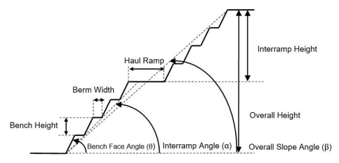
The main geometrical components of a slope are:
- Bench Face Angle – The angle between the horizontal plane and the bench wall. In most hard rock open pit mines, this parameter has values ranging between 55 and 80 degrees.
- Bench Height – The height, which typically has to adapt to the loading equipment operating the mine.
- Berm Width – The distance between the toe and crest of a bench.
- Inter-ramp Angle – The angle between the toe of a slope where a ramp segment passes and the toe of a bench located immediately upwards.
- Overall Slope Angle – The angle made with the horizontal of the line connecting the lowest toe to the uppermost crest.
- Global Slope Height – The height projected in the vertical axis between the lowest toe and the uppermost crest.
- Ramp – The road along which the trucks haul the material between a loading point and a destination.
Similar concepts can be applied to dump lifts.
Slope Regions
There are three ways of defining slope regions in a project. Only one slope region methodology can be used per design. The three methodologies are:
- Manual
- Planning Model
- Boundary Strings
Slope Region Volumes
Slope regions may explicitly define a volume using either:
- Planning Model: Blocks in a block model containing the same value of a Region ID attribute
- Boundary Strings: Outlines in a plan projection that are considered to have infinite influence in elevation
Manual slope regions do not include the explicit definition of a volume. Their volume of influence is defined by assigning them to one or more benches/lifts. Each item has an elevation and a height.
Note: There is always a fixed slope region called DEFAULT whose volume covers the entire pit. If a bench has not been assigned either a slope region or its own values the DEFAULT slope region is used.
Rosettes
Slope regions can optionally include one or more rosettes. Rosettes comprise a location and a set of azimuths each of which has a set of the three standard control values (face angle, standard and catch berm widths).
Rosettes have a minimum and maximum elevation to define their volume of influence. The horizontal influence of a rosette covers the entire slope region in which it is contained.
Each rosette is given an X, Y location. The X, Y location is only used when multiple rosettes are being used to interpolate the projection values a string point.
How Rosettes Work
When using a single rosette to determine the projection control values at a point, the direction azimuth of the projection is used to locate the corresponding azimuth in the rosette. The X,Y location of the rosette is NOT used. The elevation constraints are always used.
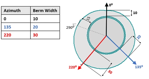
In the diagram below a circle is being projected using the rosette parameters in the table. If a point is being projected at an azimuth of exactly 0⁰ the berm width is 10. If a point is projected at an azimuth of 220⁰ the berm width is 30.
There is a gradual change in berm widths between the specified azimuths. If a point is being projected at 290⁰ the berm width will be 15, i.e. mid-way between 0 and 30.
Face angle values are determined using the same methodology for berm widths as described above.
Multiple Rosettes and Interpolation of Control Values
For pits or dumps in more advanced stages of design it is common for slope regions to contain at least one rosette, for example to force temporary internal walls to have a shallower angle than final walls which due to their longevity warrant the extra cost of being blasted using pre-splitting.
For more complex geotechnical configurations, or perhaps in an early study using a single default slope region, multiple rosettes may be used. In this case an interpolated value at a projection point is calculated by using each of the relevant rosette values.
The influence of each rosette can be adjusted by assigning it an inverse distance weighting (IDW Power value) which is used in the interpolation. If no IDW Power value is assigned then nearest neighbour interpolation is used.
Rosettes Reminders
- The X,Y location of a rosette is only relevant when interpolating values from multiple rosettes.
- The direction of projection of a point is used to determine the corresponding rosette azimuth values. A single point on a design string may have up to 2 projection directions: one for each of the adjacent edges.
- The X,Y location of a rosette may be outside the volume of the slope region in which it is being used.
- Each rosette belongs to a single slope region
Bench Level Slope Control
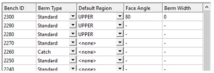
The Berm Type can be defined for each bench to define which berm width value is used (standard, catch or none). Other values can be provided but are only used if the point does not fall within a defined slope region (as defined in the slope region boundary strings or model), or if the values associated with that region are absent. See the flowchart at the end of this note for a detailed breakdown of which values are used.
Note: If a bench is set use a slope region that contains a rosette, the elevation constraints of the rosette must include the bench elevations for the rosette to be used.
Slopes Between Regions
Because Studio OP has flexible controls for defining geotechnical constraints it is possible to specify dramatic changes in berm widths and face angles over very short distances. For example, when using contiguous slope regions without rosettes that have substantially different control values, or when individual rosettes have significantly different values at closely spaced azimuths.
Studio OP has a range of conditioning and blending options to prevent these abrupt changes resulting in impractical shapes.
Auto regeneration of the design uses blending and conditioning between areas of varying face angles and berm widths to avoid creating impractical pit shells.
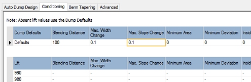
Blending Distance, Max. Width Change, and Max. Slope Change are all applied before roads are added and can be used to minimise the issues caused by rapid changes between and within regions. Minimum Area, Minimum Deviation and the Inside and Outside Fillet Radii are all applied after the pit has been modified by roads and constraints.
Blending Distance
The blending distance recognizes that there are rarely hard discontinuities between slope regions, and models dilution between the regions. This is essentially the same as shrinking each region by the blending distance, and gradually interpolating the values between them.
In this example, we have 3 adjacent regions with three different berm widths:
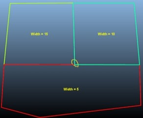
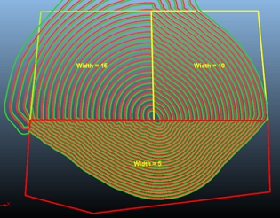
The instant rapid width changes between regions cause issues in the pit design, and would not be practical for mining:
Added a blending distance of 100 allows the berm width at region boundaries to change at a more sensible rate:
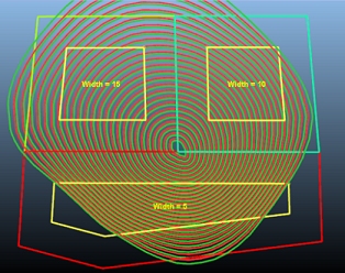
Requested widths are honoured within the reduced regions and symmetrically taper from one to the other in the gaps between regions. The blending is in all directions, not just along the toe and crest lines (so in the example above some regions are being blended into the surrounding default region (width = 20)).
Note: Blending tapers values symmetrically across region boundaries, and blending does not adjust values which vary within regions, such as from rosettes.
Maximum Change s
The symmetrical nature of the Blending Distance algorithm may cause issues if geotechnical validation is applied too rigorously in the blending regions. It can also be affected by nearby regions which the design string does not pass through, which may be a problem if the pit extends near to the edges of the slope regions strings or model.
Also, since it is designed to minimise changes between regions, it cannot be used to minimise changes within a region, for example introduced by a rosette and a design string with a rapidly changing azimuth.
An alternative approach is to use the Maximum Width Change setting or Maximum Slope setting. When a design string is projected to form a berm or a slope, it can first be processed to ensure there are no sudden changes in requested berm width or slope angle along the string. The Maximum Width Change value is the amount the requested width can vary for each unit of distance along the string. The Maximum Slope Change is the same principle in change in face angle in degrees allowed for each unit of distance along the string. Note that since this applies to values stored on the string:
- It is unaffected by nearby slope regions the design string does not pass through
- It will reduce changes within regions, as well as between them
- It can be used in conjunction with Region Blending
- It will always favour the safest value (i.e. it will never make berms narrower or faces steeper)
In the example below, the region blending has been replaced by a Maximum Width Change of 0.05.
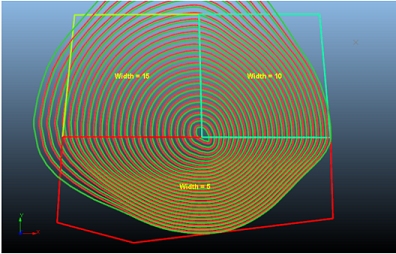
Note that the Width=10 region (top left) retains its width through the region, and the berm taper down to the narrower requested widths in the other regions.
Related topics and activities: