
Auto Design - Advanced Settings
To access this dialog:
-
Display the Auto Pit Design panel and select the Advanced tab.
-
Display the Auto Dump Design panel and select the Advanced tab.
Note: This task is part of Interactive Pit Design functionality.
Note: These settings apply to all pit or dump design scenarios.
Use these settings to control advanced behaviour for automated pit or dump designs. This includes how the in-pit or in-dump road is assessed when applying gradient values defined on the Auto Pit Design tab.
For pit designs, you can also define an evaluation legend used to evaluate the theoretical pit phase solid formed by intersecting an automated design with the topography assigned to the current pit.
Pit Evaluation Settings
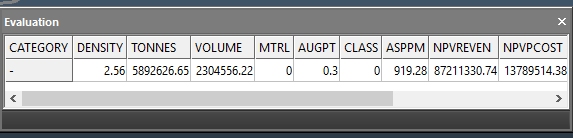
If you choose to automatically evaluate your calculated design surface, results are output to the Design Evaluation control bar. If no legend is specified, Studio checks whether one has been set up using the Reserves >> Evaluate task instead. If no legend has been configured there either, TONNES and VOLUME (and other attributes) are reported against a single (-) category, for example:
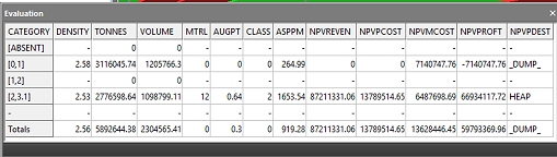
When an evaluation legend is specified (either on this panel or in the Reserves >> Evaluate task), categorised results are calculated automatically, for example:
Note: You cannot define an evaluation legend when producing dump designs, because volume calculations (per lift) are performed instead without block model interrogation.
To produce evaluation results (for pits or dumps), a topography must be associated with the selected pit, and it must be possible to create a closed volume between the generated design surface and the topography. The closed volume is evaluated, so a missing topography prevents evaluation results from being calculated.
General workflow:
-
Display the Auto Pit Design or Auto Dump Design task.
-
Activate the Advanced tab.
-
Choose how a road’s gradient is determined when generating design strings:
-
Steepest – All new projects, or unmodified projects, use this setting by default. Studio determines which side of each road segment is steepest and constrains the gradient on that side. This is useful when the projection produces a complex road shape, for example an “S”, where there is no consistent inner or outer edge. This can also apply when a switchback has been inserted.
For example, the pit road below is a switchback road from the pit base to the pit rim:
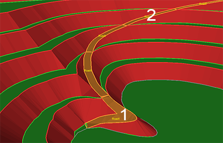
In this example, the goal is to apply a fixed gradient to the entire road of 12 degrees. The inside edge (on the pit void side) of Segment 1 is steeper than the outside, so the gradient setting (12 degrees) is applied to the inside edge. Segment 2 is the opposite: the outside edge is steeper than the inside edge, so the gradient is applied to the outside edge.
These settings affect how adaptive roads are positioned. The following image shows the same road positions calculated by changing only the Road Gradient Side setting:
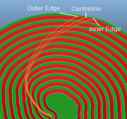
Compared with setting the gradient consistently to the outside edge, the Steepest option always applies the gradient on the steepest side.
-
Pit inside for Bottom-Up, Pit outside for Top-Down – Choose a road side for gradient constraint based on the generation direction: inside for bottom-up designs and outside for top-down designs.
-
Pit/Dump Inside – Fix the road gradient on all road segment edges on the pit void side or the dump face side, regardless of projection direction.
-
Pit/Dump Outside – Fix the road gradient on the pit wall side or the air side of the dump, regardless of projection direction.
-
Centreline – Set the road gradient at each road segment’s centreline.
-
-
Gradient Search – For gradient fitting, define how close a fit is acceptable, or how many attempts Studio makes to find the best-fit gradient for your road. A search is performed to find the best fit for your road and gradient (plus any other constraints), and a maximum number of iterations is used to find an optimal solution, stopping when all parameters have been satisfied.
-
Tolerance – How close the defined gradient must be to the specified constraint. For example, your operational setup may permit a tolerance of plus or minus 0.25 degrees. Smaller tolerances tend to increase calculation time.
-
Max. Iterations – How long you want to spend finding the optimal solution. Increasing this value can increase processing time, but can also produce a result that more closely matches gradient constraints.
If a gradient is not found at the required precision after the maximum number of iterations, the best solution found so far is used, and a message is sent to the Output bar outlining the road, elevation, and the quality of the final fit, for example:
Road Error: Road1 gradient could only be matched to an error of 5.02628 degrees between elevations 0->20
-
-
Choose the legend and data attribute used for phase volume Evaluation.
This legend is used in preference to any other evaluation legend configured within the current project, so it acts as an override legend.
Tip: Use the Pit Data control bar to display your planning model so you can quickly review your evaluation legend.
To force a particular evaluation legend to be used, select Override Default Legend, which enables the following options:
-
Legend – Select a legend that represents evaluation categories for the selected Column. You can also select <none>, which reports only the accumulated total TONNES and VOLUME for the generated phase volume.
-
Column—Select the numeric data attribute to evaluate. If <none> is selected, summary TONNES and VOLUMES are calculated for the phase volume.
-
-
Choose whether to use Use full cell evaluation:
-
If Use full cell evaluation is checked, model cells are treated as wholly inside or outside the wireframe. If more than 50 percent of a cell’s volume is inside the wireframe, the cell is included and all its volume is evaluated. This is quicker but less accurate than partial cell evaluation.
-
If Use full cell evaluation is unchecked, partial cell evaluation is used, meaning partial cells within the wireframe contribute to an evaluation tonnage or volume. This is more accurate, but slower than full cell evaluation.
-
-
Choose a Projection Method to control how toe and crest strings are rounded. For example, you can make tight curves more angular (for blast design) or more curved (for smoother representation).
Related topics and activities