
Create Contact Surface: Faults
This topic explains how fault data can be integrated with contact
surface modelling calculations.
Fault Modelling
Wireframe sheets are used to differentiate independent blocks of data. These 'fault blocks' are modelled to mimic the natural outcome of material shear/thrust.
If multiple fault wireframes are required they must be contained within the same wireframe object and attributed with a unique ID within a dedicated table column.
- The Fault Surfaces drop-down list is used to select a loaded wireframe object containing one or more fault wireframes
- The Fault ID Column drop-down list is used to determine unique fault wireframes within the loaded data. If <none> is selected, the full wireframe file will be treated as a single faulting structure.
Tip: Fault wireframes can be modelled quickly and easily using the Model Faults managed task.
Once a Fault ID column has been selected, the loaded fault wireframe will update automatically to highlight the different Fault ID values within the selected attribute.
Each output fault block is assigned a unique Fault ID value. Fault surfaces within the specified fault wireframe (e.g. according to a SURFACE attribute) determine how many fault blocks are created.
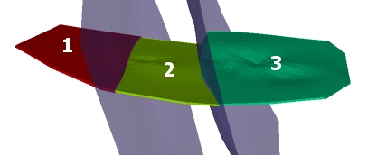
For example; in the input fault wireframe below, shown in blue, the SURFACE attribute is used to define two separate fault sheets. This produces three output fault blocks, each with a unique FaultID.
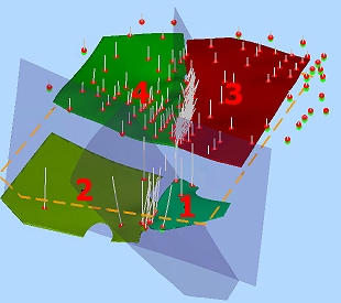
In the following example, 3 fault sheets are used to split modelling output into four fault blocks. All fault wireframes fully intersect each other, although they don't have to:
Tip: To isolate fault blocks as individual wireframe data objects, use the Extract Data Object function. To visualize them independently without changing the underlying data, use the Quick Filter control bar.
If fault data is used, the Output window report will show the object used to generate the fault blocks and the number of fault blocks generated.
Fault Modelling Considerations
Consider the following when creating faulted contact surface models:
- Fault data must fully-dissect the output created without faulting. Partial faulting will result in the fault wireframe being ignored.
- Where multiple fault wireframes are used, ensure zero-sample blocks aren't created (this will lead to a gap in output data).
- Fault wireframes should be open surfaces, but can be any shape or alignment. Any loaded wireframe data can be used, such as an imported DXF wireframe, for example.
- Use additional points to reinforce expected output. This can be useful to shape a surface trend up to a fault, for example.
- Sample data, either positive or negative cannot influence a structure on the remote side of any fault sheet.
- Each fault block is modelled separately. Increasing numbers of fault blocks will lead to longer processing times.
- Fault blocks are output to a single wireframe object, but can be split into separate objects using Extract from Object or can be visualized individually using the quick-filter command (based on the FaultID value of the generated data).
- Your input fault wireframes should be of sufficient resolution to model the expected boundaries, but be aware that very dense fault data can lead to extended processing times.
- A custom boundary, if specified, will apply to all output data, including all fault blocks.
- You can select Use Faults in combination with any other setting, including Controls, Boundary, Edit Points and Additional Points commands.
- Faulted cases will honour pre-selection. This can be useful to constrain input data to produce expected shapes.
- If fault wireframes don't fully transect the input samples (actually, the hull formed by them), the intersecting fault wireframe surfaces must meet completely or actually cross over each other. Otherwise, a fault block may not be formed correctly.
-
Fault wireframes must project fully above and below the sample data.
Related topics and activities