Format Landmark Symbols
Note: A Datamine eLearning course is available that covers functions described in this topic. Contact your local Datamine office for more details.
There are two types of drillhole overlay symbols; landmark symbols and structural symbols.
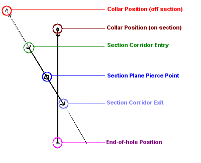
The following activity describes how to display landmark symbols. These have a fixed location and represent key positions that identify the direction of the drillhole and how it is positioned with respect to a 3D display section. Collar and end-of-hole positions, for example, are drillhole landmark positions.

Drillhole landmark points
This activity references controls in the Symbols command group of the Drillholes Properties: Symbols screen.
Activity steps
- Display drillhole data in any 3D view and display the Drillholes Properties: Symbols screen.
-
To display a symbol at the Collar, Section plane pierce point, Section plane entry and exit or End of hole:
-
Check the landmark position to display (you can display none or any).
-
For each checked landmark symbol, specify the Size.
-
Choose how the size value will be interpreted using the menu to choose either World (Size = world measurement units) or Screen (Size = pixels).
Note: World-scaled symbols will scale with the view but Screen-scaled symbols will be shown at the same size regardless of the view magnification.
-
Pick a Symbol to display:
-
Choose a symbol collection using the menu provided. Symbol collections can vary between products. See Symbols.
-
Pick a monochrome symbol.
-
-
If required, choose a custom colour. If unchecked, the system default colour will be used.
-
Check the Color box.
-
Expand the colour menu to pick a colour.
-
-
- To display Sample ticks (the point at which a new core sample begins) or Depth intervals (markers at fixed distances down the hole):
- Check the appropriate item.
- Choose if the ticks or markers will appear to the Left, Centre or Right of the drillhole. This represents the initial display; ticks or markers will rotate with the data if view changes are made.
Choose how the size value will be interpreted using the menu to choose either World (Size = world measurement units) or Screen (Size = pixels).
If defining Depth intervals, specify the distance between intervals using the Every field.
Pick a Symbol to display:
Choose a symbol collection using the menu provided. Symbol collections can vary between products. See Symbols.
Pick a monochrome symbol.
If required, choose a custom colour. If unchecked, the system default colour will be used.
Check the Color box.
Expand the colour menu to pick a colour.
Related Information and Activities

