|
|
Surface Reconstruction from Points Applying a surface to an input point cloud |

|
|
An online tutorial covering point reconstruction commands can be found here: (Internet connection and Datamine Support Portal login required - contact your Datamine representative if you need assistance). |

Surface Reconstruction from Points
There are three access points for this dialog:
-
Enter wireframe-create-from-points into the Command line.
-
Enter gaussian-wireframe-from-points into the Command line.
-
Reconstruct surfaces implied by point cloud data.
|
|
Although this command can be used to generate either volume or DTM surfaces, it is primarily design to generate the former. For a more focussed DTM generation command, see dtm-create. |
There are two variations of this function:
- Standard mode: this is the function launched using the wireframe-create-from-points command. It uses an optimized, rapid surfacing routine to find the optimal surface to honor input point data (declustered or otherwise). This launches the Wireframe Reconstruction from Points dialog.
- Gaussian mode: this is launched using the gaussian-wireframe-from-points command and is an alternative to the above. It launches the Wireframe Reconstruction GP from Points dialog. The gaussian alternative features more control over data uncertainty and may provide a more continuous surface with points representing surfaces with severe direction changes and/or less predictable trends. This comes at the cost of processing time.
The information on this page applies to both commands unless otherwise stated.
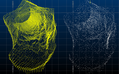
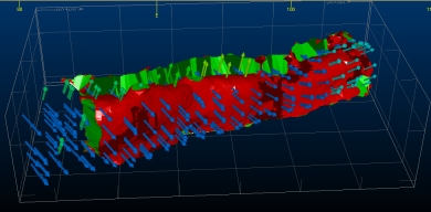
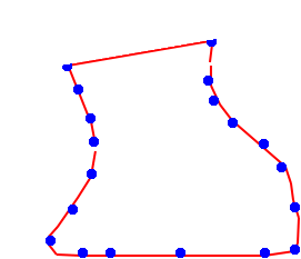
In the images below, the left image was created using wireframe-create-from-points, surface a subsampled point cloud data set (10k points) with an average distance between points of approximately 1.0m, using high performance mode and all other default settings. This took approximately 15 seconds to create.
The right image shows an equivalent output from the gaussian-wireframe-from-points command using the same point cloud and equivalent settings. This took approximately 2m to complete:

What isn't obvious from the above image is that the gaussian surface has a slightly closer adherence to the input samples and picks out surface features more clearly than the standard output. Both are arguably suitable for further analysis, modelling and evaluation functions.
See Point Reconstruction Methods and Tips.
User Input
Both commands should be used with the following general procedure:
- Select the points to surface in the 3D window, then run the command - these commands will ONLY operate on selected point data.
- Load raw point data and subsample/decluster (optionally) to provide a subset for surfacing. You can create multiple point cloud variations if you wish. If duplicate points are detected in the input points file, only one of the points will be added to the point cloud object.
- Select the point cloud you want to surface.
- Set up how you want to surface your data.
- Calculate a best-fit surface to the points in the cloud, honoring surfacing parameters.
You can control the resolution and application of the resulting mesh. Granular control is provided over how the mesh triangles are generated in relation to the underlying source data.
On completion, a single wireframe mesh will be created (as a pair of physical .dm files on disk, and a single wireframe object in memory), honoring the positions of all points present in the original data file. Note that if your file contains multiple point "clouds", and independent surfacing of each zone is required, it will be necessary to filter this file and create independent source files before you start. In summary: this command will produce a mesh taking into account all of the points of the input data alongside other function parameters.
This command can be used to generate both closed wireframe volumes and digital terrain models (DTMs). In the latter case, you will be able to specify how a wireframe mesh is 'laid' onto the imported points, e.g. from which direction.
This command is intended for use in conjunction with point cloud
data that is of sufficient resolution to indicate a surface or volume.
Controls on this dialog should generally be used in a top-bottom order.
Field Details:
Input Point Creation
The controls in this group are used to define how the loaded ("raw") input points file is prepared and converted to a "Point Cloud" for surfacing. The Point Cloud is a distinct data object borne from the original input. This approach allows you to experiment with various point preparation options based on the same input file.
Input Points | No. of Input Points: select from a list of points objects in memory. The read-only field on the right shows the total number of points currently being considered for surfacing. If no points are selected, all points in the selected object are considered, otherwise, selected points will be considered.
Points will be prepared (subsampled, if required) then the result committed to the cloud for surfacing when you click Create Points.
You can modify the selection group whilst the Surface Reconstruction from Points dialog is open.
Subsample: subsampling reduces the number of points to be considered during surfacing. By default, all selected points will be considered (None) but you can also elect to remove points based on a regular grid and attempt to meet a target number (Uniform) or a method that will thin out density 'clusters' where they are found (Decluster).
The example below shows a raw input data set on the left (20,000 points) and the to-be-surfaced set after subsampling to meet a target value of 5,000 points:
Direction Calculation Controls
The controls in this section determine how surface normals are calculate during reconstruction.
Maximum
Considered Points:
this parameter controls how the normals of the points are calculated.

Generally the default value is suitable. The value is used to
determine the optimum ‘normal’ direction of each subsampled point.
These normals indicate a 3D direction and are used to control how
surface triangles are generated.
-
Lower values consider less points to determine the most appropriate normal, whilst quicker it is possible to set the bar too low, resulting in neighboring normals with very different directions – these are difficult to surface with realistic continuity.
-
Higher values consider more points to implement a more gradual change in normal direction across the surface, at the expense of higher processing times. It is also possible to set this value too high, causing the normal directions of points to be influenced by too many neighbors.
Maximum Considered Points must be greater than or equal to 10. The default is 50.
The Smooth Corners option can be selected to introduce a more gradual surface change where the surface is interpolated.
Internal Strings: when computing a surface, the normals of a point determine how a surface is ultimated wrapped around the point cloud.
Studio will attempt to find a normal direction for each point that represents the optimal solution, but in some cases, the surface that is required is the result of a more subjective/intuitive process. You can use a loaded string as a basis for orienting normals within your cloud of points.
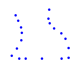
For example, the following points represent scan lines down a tunnel:
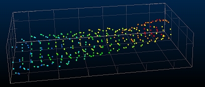
If you enable Display Normals (see below), you
can see that the normal direction for some of the points is not ideal,
and could cause wireframe triangles to be created at an unexpected
angle: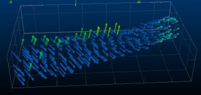
This gives rise to
the following output wireframe with default settings:
Digitizing or loading a string throughout the body of the point cloud
can help 'guide' the normal creation, e.g.: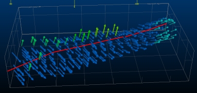
Recreating the point
cloud then results in normals that radiate outwards from the 'centre'
of the point cloud: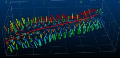
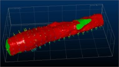
As wireframe triangles will be positioned orthogonally to the direction of the normal, this is a good candidate set of points for surfacing.
Generating the wireframe in this case is a clearly superior result:
Point Cloud Points: enter a
name for your point cloud object. This will contain the (optionally)
subsampled input points. Use Create
Points to create the point cloud that will be used for surfacing.
This also generates general statistics about the point cloud, as shown
in the right-hand panel, e.g.:

Creating points will add a new object to the Point Cloud Input drop-down list (see below).
Once a point cloud exists, you can show it as either points or normal arrows, using the Display Normals check box. The latter is very useful to see how the surfacing engine will attempt to create a volume/surface.
|
|
If duplicate points are detected in the input points file, only one of the points will be added to the point cloud object. |
Create Points: generate the points to be used for surface reconstruction. This creates a "Point Cloud" that can be selected and parameterized in the section below in order to produce the desired reconstructed output.
This section relies on a loaded Point Cloud object, generated using the Create Points function above. The following controls are then used to determine how the surfacing is performed:
Point Cloud Input: select a point cloud object from the list. Statistics information will update to show the selected object when this value changes. When a point cloud is selected, default values for surfacing are also set (Search Radius and Remove Holes) based on the average distance between points.
Dynamic Factor: similar to the Uncertainty value (see below) in that it represents a measure of how close a gaussian curve will be fitted to the sample points during surface generation (only available with gaussian-wireframe-from-points).
Uncertainty: optionally, cloud points can be assigned an Uncertainty value that will allow a best-fit surface to be generated within a tolerated range of limits for that sample.
For example, in the image below, a surface is constructed initially with zero uncertainty (red). The next run, a value of 0.1 is used which allows the resulting surface to pass close to, but not necessarily through, the point (green).
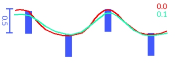
(only available with gaussian-wireframe-from-points).
Search Radius: the distance that is 'searched' to find neighboring points. Larger radii will produce more continuous surface features and smaller radii are likely to introduce more surface features/deviations, although this is dependent on the density and arrangement of points in the cloud. For regularly spaced points, the default value is likely to be more suitable than for irregularly-spaced, clustered data.
Remove Holes <: this is a perimeter setting. If 3 triangle edges are less than the specified length value, the inter-edge space will be surfaced, otherwise it will be considered a 'hole'. This will be left open if Close wireframe is deselected (see below).
Resolution: a value controlling the resolution of the points within the bounding cuboid (N x N x sample set height). A higher number will result in more dense wireframes but will take proportionally longer to calculate surfaces.
Performance: choose between a higher processing time but more accuracy (Low), a balanced approach (Medium) or a rapid, less accurate method (High).
Close
holes: if selected (default), the surfacing engine will attempt
to close gaps regardless of size. For example, the image below is
surface without Close wireframe
enabled on the left and with it enabled on the right:
Where a surface is created to close a wireframe, a different SurfaceType attribute is used - this allows you to see the impact of closing a wireframe vs. leaving it open.
For DTMs, you should always leave this check box unselected, or, if you wish to use a more appropriate command, use dtm-create.
Limit Extrapolation: where point data is sparse, Studio will attempt to span the gap whilst continuing the trend of the neighboring points. Where points indicate that a volume should continue in a given direction, but then sparse data exists, the interpolation will continue the direction of the surface to attempt to create a manifold surface.
Consider the following example, showing a cross section of a point cloud (although the actual problem is 3-dimensional). The area at the top contains 2 widely separated points:
The surface that 'resolves'
these points is ambiguous - how should the gap be closed? The answer
will depend on the neighboring points, but is also largely subjective.
By default, Studio will attempt to continue the trend of the neighboring
surface in order to preserve its overall integrity, e.g.: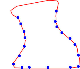
Selecting Limit Extrapolation will reduce the amount the surface is extended under these conditions, e.g.:
Output: name your output wireframe object. You can overwrite existing objects by selecting them from the drop-down list.
Create Wireframe: click this when you're ready to surface your point cloud. Processing time will depend on the number of points and the settings made above.
|
|
Related Topics |
|
|