|
Project Data - 3D - ROM Stockpile Boundaries |

Project Data - 3D - ROM Stockpile Boundaries
To access this menu:
-
Display the Project Data control bar, expand any 3D window folder and the ROM Stockpile Boundaries sub-folder.
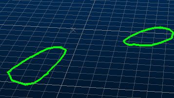
The Project Data control bar's 3D ROM Stockpile Boundaries folder is used to display overlays based on surface data that has been loaded from your Studio Survey database (loaded local files will never appear in this folder, only database-bound information).
These files represent perimeters used to constrain the generation of cut-and-fill stockpile volumes using the ROM reporting tool.
3D objects (loaded file data) can be represented by one or more visual overlays. All overlays are listed here, and are independently configurable. Each item is supported by a context menu providing access to a range of overlay-specific functions as well as object-specific functions. It is important to remember that if you edit the underlying object data in any 3D window (e.g. moving a wireframe vertex, or adjusting a boundary string node), this change will be represented in all overlays associated with that object.
Double-click a folder item to display the corresponding String Properties dialog.
Context Menu details:
Right-clicking an item within this folder shows the following menu options:
Save: save the current overlay's data object without further prompts. For this option to be available, you will need to have already saved the associated object in memory to a file (e.g. using theData | Save Asoption - see below).
Note that you will only be able to save to the associated data file if it is writable, and you have the relevant access permissions.
Data: this option cascades the following sub-menu:
-
Reload...: reload the selected object into memory using new load/import settings.
-
Refresh...: refresh the selected object into memory using its associated data load/import settings.
-
Save As...: save the selected new 3D object to the project file or a new Datamine file. This option opens the Save New 3D Object dialog.
-
Export...: export the selected object to a Datamine or non-Datamine file, using the Data Export dialog.
-
To Excel...: export the selected object's table and open it in MS Excel. This provides an quick means of exporting data to *.xls format.

Microsoft Excel only supports a finite number of data rows, therefore, this option is not suitable for large data sets that have more data rows than this. If such a situation occurs and you are using Excel 2007, only the first 65535 rows of data will be displayed.
-
Unload...: unload the selected object data from memory.
")
This does not remove the file from the project (i.e. it remains listed in the Project Files control bar), nor does it remove the file from disk.
Copy Data From: append the selected object with data from another object of the same type using the Select Objects to Copy From dialog.
Extract: derive information held within currently loaded data objects, and create new objects based on the values contained within a selected field. Displays the Extract Data Object dialog.
Add Column: add a new attribute to the data object to which the overlay relates, using the Add Column dialog.
Make Current Object: to assign the data object associated with the selected overlay as the "current object", select this item - subsequent interactive 3D editing will be performed with respect to the current object. More about the current object.
Select All: select all object overlays of this type.
Deselect All: deselect all object overlays of this type
Data Object Manager: displays the Data Object Manager, with the associated data object selected for further analysis. More...
Apply Clipping: by default, 3D window clipping will be applied to all object overlays once clipping is activated. You can choose to disable or apply clipping to any overlay independently using this toggle option. View clipping will only be applied to overlays that are 'clipping-enabled'.
Rename: rename the current 3D overlay.
String Properties: opens the String Properties dialog, open at the General tab.
Use Template:
if you have defined one or more 3D display templates for the selected
overlay, you can see them listed here - simply select a template to automatically
update your currently-active
3D window view. This is particularly useful for checking one domain against
another, e.g. rock type against a grade.
Note that this menu option will only appear if at least one 3D template
has been defined for the selected overlay.
Copy: creates an identical, automatically named copy of the selected object (note that there is no requirement to paste the item - the list of objects will be updated automatically). Copied objects have no link to their origins; changes to the original object will not affect the duplicated item, and vice versa.
Look At: automatically positions the 'camera' to show the selected string.
Look at Individual String: displays the Select String/Drillhole dialog to allow you to select a string entity within the associated data object. More...
Redraw: refresh the view of the selected object in the active 3D window.
New String: enables string creation mode, used for the creation of alignment strings. For more information on creating this type of data in 3D , see Digitize and Edit.
Project to Wireframe/Section: fit the current object to the nearest wireframe surface or section, using the Project Strings/Points dialog. Objects will be projected along the line of view until each vertex rests on a surface. More...
Convert to Planes: creates a new plane object from an existing string (open or closed). An average plane is created which best fits all points in the string. Please note that a valid SiroJoint license must be installed in order to use this command. More...
Quick Legend: creates a numeric legend using theQuick Legenddialog.
Display Legend: preview the legend that is currently associated with the 3D object.
Legend Column: select any data field within the parent object from which the 3D overlay was created. Once selected, the currently associated legend will be applied to the new column. Note that the fixed color will be used for any unmatched data.
Rename: rename the selected 3D overlay.
Delete Strings: removes the selected object from the project.
|
|
Each item within theStringsfolder can also be expanded to show a list of all vertices that make up the selected string. This areaalso has a dedicated context menu comprising the following commands:
|
|
|
Related Topics |
|
|
Wireframe
Properties - General DialogAdd To Database
ROM Reporting toolStudio Survey Database OverviewProject Data Control Bar |
Copyright © Datamine Corporate Limited
JMN 20045_00_EN