|
|
Volumetric Block Modeling Dialog How to use this dialog for generating block models using wireframes |
Volumetric Block Modeling
To access this dialog use one of the following:
-
Run the command model-from-multiple-wireframes.
-
Use the quick key 'mfw'.
This dialog is used to generate a single or composite block model from one of more wireframes, optionally using perimeters for additional control.
Combining Block Models
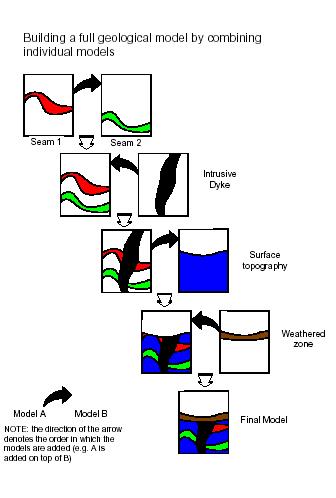
The order in which block models are combined is important. The following diagram shows the sequence in which individually modeled features need to be added in order to create a composite block model:
Subcelling
The generation of accurate block models is achieved by a using a combination of the parent cell size parameters (defined in the prototype) and the various settings which control the orientation and size of the subcells splitting. These include the options and values defined in the Plane, Subcelling group and Optimize Subcells fields of the Volumetric Block Modelling dialog and are described further below. The examples are based on a topographic surface using a value of Plane = [XY] which means that splitting is regular in the XY plane but variable in Z. The principles are identical if splitting is in one of the other planes.
Only cells that are intersected by the wireframe are split into subcells. All others remain as parent cells.
Using the 'Define Number of Subcells' Parameters
The degree of splitting is controlled by the X,Y,Z and Resolution parameters. These specify the number of subcells to be created in the two directions defined by the Plane parameter and the size resolution in the perpendicular direction defined by the Resolution parameter.
For example if X=2 and Y=4, then 2 subcells are created in X and 4 in Y and the value of Z is ignored. This is illustrated in the images below.
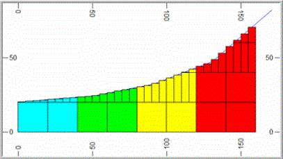
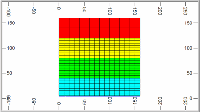
The Resolution parameter controls the size of the subcell in the direction perpendicular to the plane defined by the Plane parameter. In the examples given above Plane = [XY] and so Resolution controls the size in the Z direction. If Resolution = 0 (the default) then the subcell size in Z is calculated exactly, from the elevation of the point where a wireframe triangle crosses the mid point of the subcell in X and Y. This is illustrated in the two examples above where it can be seen that the wireframe intersects the midpoint of each subcell. Resolution must be set to an integer value.
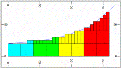
If Resolution is greater than zero then the cell size is rounded to the nearest ZINC/Resolution where ZINC is the parent cell size in Z. For example if ZINC=20 and Resolution=4 then the cell size in Z is rounded to the nearest 5m as illustrated in the image below.
Using the 'Dip of Wireframe' Parameters
Here the degree of splitting is dependent on the dip of the wireframe. With Plane = [XY], this means that there is little or no splitting where the surface is approximately horizontal but increased splitting as the dip of the wireframe increases. This is controlled by setting a Reference Dip value, in degrees. Then for each parent cell that is intersected by a triangle, the maximum dip of all triangles, intersecting or adjacent to the parent cell, is calculated. The definition of adjacent is a rectangular area of dimensions 2*XINC by 2*YINC centred on the parrent cell centre, where XINC and YINC are the parent cell dimensions in X and Y. The amount of splitting is then defined by the ratio of the maximum dip of intersecting or adjacent triangles to the Reference Dip value as shown in the table below.
| Ratio | Calculated Number
of subcells |
| < 2 | 1*1 |
| >= 2 < 4 | 2*2 |
| >= 4 < 8 | 4*4 |
| >= 8 | 8*8 |
The Max Subcells parameter is used
to define the maximum level of splitting. In the above
table it is assumed that Max Subcells=8*8.
If it were set to 4*4 , the maximum number of subcells would
be 4*4 even if the ratio exceeded 8. The same level of
splitting is always applied in both the X and Y directions.
For example let Max Subcells be set
to 8*8 and the Reference Dip=5o.
If the maximum dip of triangles intersecting or adjacent to the cell
is 11o then the ratio is 2.2, so there are 2*2 subcells. If
the maximum dip of triangles is 35o then the ratio is 7,
so there are 4*4 subcells. This is illustrated in the
South-North section below (left) where the slope of the wireframe
increases from left to right. The surface for all East-West
sections is totally horizontal. The plan (right) shows
the cell structure at an elevation of 21m where the parent cell size
is 20x20x20m.
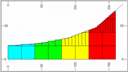
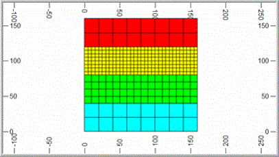
If Reference Dip is set to 0o then the ratio is infinity and the cell is always split. The degree of subcelling will then be independent of the dip ratio and only dependent on the Max Subcells parameter. If Reference Dip=0 and Max Subcells=4*4 then all parent cells that are intersected by the wireframe is divided into 4*4 subcells in X and Y.
Field Details:
Modelling Settings Control File: use these controls to optionally define, save and load modeling settings to or from an external parameters control file.
Control File: define a new or browse for an existing control file (*.dm, *.dmx).
Save: click this button to save the dialog's currently defined parameters to a settings file.
Load:
click this button to load a set of parameters from a modelling settings
file.
Prototype Block Model:
Block Model Prototype: browse and select a block model prototype file; this can either be a a block model or prototype block model. The records in a block model are ignored; rotated block models or prototypes can also be used.
Create
Model Prototype: click this button to open the Create Model Prototype dialog.
Control Perimeter: optionally select a perimeter (strings) file in order to restrict block filling within the wireframe(s) volume(s) to an area lying within the selected perimeter.
Perimeter: browse and select a strings file.
|
|
|
Preview:
click this button to view the selected perimeter file in the Preview dialog.
Boundary Wireframes: use this group to select one of more DTMs or solid (closed) wireframe files; each file can contain one or more wireframe surfaces. For each selected wireframe file, define the following:
When creating a composite block model from multiple wireframe files, the order in which the files are listed in the Boundary Wireframes grid is important, as this order defines the sequence in which the individual block models are combined. Please see the Combining Block Models section below for further information. |
Run: select this option to use the listed wireframe in the block modeling process.
Topo: select this option if the wireframe is a DTM which defines the surface topography (top or bottom) of the block model; any cells lying below (or above, depending on the selected Boundary Type) the topography is removed. The state of this field determines what Boundary Type options (see below) are available.
Wireframe: browse for a wireframe triangle file. The Run option is automatically set when a file is selected.
Zone Field: select an existing zone control field from the drop-down, or type in a new field name. All fields in the selected wireframe are listed in the drop-down. The default is ZONE, even if this field is not present in the wireframe.
Zone Code: define a zone control value for the cells filling the selected wireframe. This option is disabled if the selected Zone Field is present in the wireframe and '(From Field)' is displayed. In this case, the value is taken from the wireframe(s). If a new Zone Field is defined, the default Zone Code value is set to '0'.
Plane: using the drop-down, select one of the following options:
[XY] - subcell splitting is regular in the XY (horizontal) plane, but variable in the Z direction; this option is typically used for DTMs or solids which have a low dip
[XZ] - subcell splitting is regular in the XZ (west-east) plane, but variable in Y; this option is typically used for DTMs or solids which have a moderate to steep dip and are striking approximately west-east
[YZ] - subcell splitting is regular in the YZ (north-south) plane, but variable in X; this option is typically used for DTMs or solids which have a moderate to steep dip and are striking approximately north-south
Care must be taken in selection of the plane to be used if the ends of the wireframe have not been linked i.e. closed, as the wireframe model is then partially 'hollow' when viewed from certain directions. |
Boundary Type: using the drop-down, select a boundary type for the wireframe:
If Topo is selected, the following options are available:
[Single Surface - Fill Above] - select this option to fill above the DTM
[Single Surface - Fill Below] - select this option to fill below the DTM
If Topo is not selected, then the following options are available:
[Solid - Fill Inside] - select this option to fill inside the solid (closed) wireframe
[Solid - Fill Outside] - select this option to fill outside the solid (closed) wireframe and within the prototype limits
[Single Surface - Fill Below] - select this option to fill below the DTM
[Single Surface - Fill Above] - select this option to fill above the DTM
[Two Surfaces - Fill Between] - select this option to fill between the two DTM surfaces
[Two Surfaces - Fill Above & Below] - select this option to fill above the upper and below the lower DTM surface; and within the prototype limits
The terms 'above' and 'below' are used relative to the orientation of the selectedPlaneoption. 'Above' indicates the increasing, 'below' the decreasing coordinate direction. |
Use Perimeter: select this check box in order to restrict cell filling, for the selected wireframe, to the area within the control perimeter; this option is disabled if no Control Perimeter is defined.
Density: define a default density for the selected wireframe; the default value is '1'.
Up: move the selected wireframe record up by one row.
Down: move the selected wireframe record down by one row.
Delete: delete the selected wireframe record.
Add: add a new wireframe record to the bottom of the list.
Subcelling: for each wireframe listed in the Boundary Wireframes table, select one of the following two methods for controlling subcell generation (for more information on subcelling click here):
Define Number of Subcells: select this option to control subcelling by defining the number of subcells in each direction in the selected Plane and the resolution of the subcell size in the perpendicular direction:
X: define the allowable number of subcells in the X direction (value: 1-100).
Y: define the allowable number of subcells in the Y direction (value: 1-100).
Z Resolution: define the size resolution factor for the subcells in the direction perpendicular to the selected Plane (default '0'). If this value is set to '0', the subcell size is calculated precisely i.e. defined by the point at which it crosses the wireframe. If this value is greater than zero, then the cell size in the perpendicular direction is rounded to the nearest Parent Cell Size/Resolution.
The selectedPlaneoption determines which of theX,Y,ZandResolutionoptions are available e.g. if set to [XY], then onlyXandYandZ Resolutionoptions are enabled. |
Use Dip of Wireframe: select this option to control subcelling by the dip of the wireframe within the parent cell, define the following parameters:
Max Subcells: using the drop-down select one of the maximum number of subcells options i.e. [1*1], [2*2], [4*4]or [8*8].
Reference Dip: define the reference dip value in degrees (value:0-90).
Z Resolution: define the size resolution factor for the subcells in the direction perpendicular to the selected Plane (default '0'). If this value is set to '0', the subcell size is calculated precisely i.e. defined by the point at which it crosses the wireframe. If this value is greater than zero, then the cell size in the perpendicular direction is rounded to the nearest Parent Cell Size/Resolution.
Apply
Values To All Wirefames: click this button to apply all the
Subcelling group options and parameters
to the listed Boundary Wireframes.
General Options: select one or more of the following general options:
Validate
Input: select this option (on by default) to validate the selected
input files before the modeliling process is started. The validation
checks that the extents of all the selected wireframes lie within
the block model prototype. A warning message and prompt is displayed
if the validation fails, as shown below. Clicking Yes
continue, while clicking No will stop
the modelling process: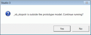
Load All Wireframes: click this button to load and display all wireframes selected for the run. Only those which are not already loaded into memory are loaded.
Tolerance: if disabled (default), the value in the edit box is based on the Prototype block model. If enabled, you can enter any value from 0 to 1 inclusive. This value is used to filter out any blocks smaller than this value (relative to the size of parent blocks).
This value (and whether
or not the check box was enabled) is also saved in the Model settings
control file when you save your settings, and is reloaded in
future dialog sessions.
Output: define a new block or browse and select an existing model file to which the modeling results are saved; any selected, existing file will be overwritten.
Block Model: define a new block model file name or browse for an existing file; the existing file is replaced.
Optimize Subcells: select this option to optimize the number of subcells in the final block model using the PROMOD Process.
Keep Intermediate Files: select this option to keep the intermediate files which are used to generate the final block model; these files can be used to validate or investigate the output from the various stages of the block modelling process. The temporary Datamine files have the prefix '_spmod'.
All previous intermediate files are overwritten before a modelling run is started. |
Progress Bar: use this to monitor the progress of the block modeling process. In addition, the output in the Command control bar can be used to view the progress details as shown below:
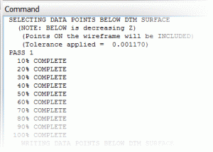
Apply: click this button to start the block modeling process using the selected files, defines options and parameters.
If the block model generation process is being run again using the same model files, and if any of the intermediate files or the output block model have been loaded into the Design or VR windows, e.g. for validation or trouble shooting purposes, please unload these first before clicking Apply. |
Stop: click this button to stop the block modeling process; this button is only enabled when Apply is clicked.
Cancel: click this button to close the dialog without generating output.
When block models are added together (using ADDMOD) in order to create the final block model, the tolerance parameter is calculated as follows:Tolerance = 0.025 / Max (XINC,YINC,ZINC). |
|
| Related Topics |
| Define
Model Prototype CDTRAN TRIFIL ADDMOD SELWF PROMOD |


