
Create Drive Solids
Drive solids are wireframes representing an underground structure, commonly used to compare surface between different time periods for the purpose of compiling cut and fill reports.
Drive solids are generated using the Drive Solid from Survey Data screen.
Preparing Input Surveyed String Data
Drive solids are constructed from underground surveyed strings. Strings must be loaded and, if required, filtered to show only data relevant to solid construction. For example, a loaded string object may contain, in addition to strings representing roof, back and walls, other data indicating laser positions and orientation, or linkage point information that would otherwise warp the constructed solid adversely.
In the following example, a surveyed string file is loaded and appears in the 3D window:
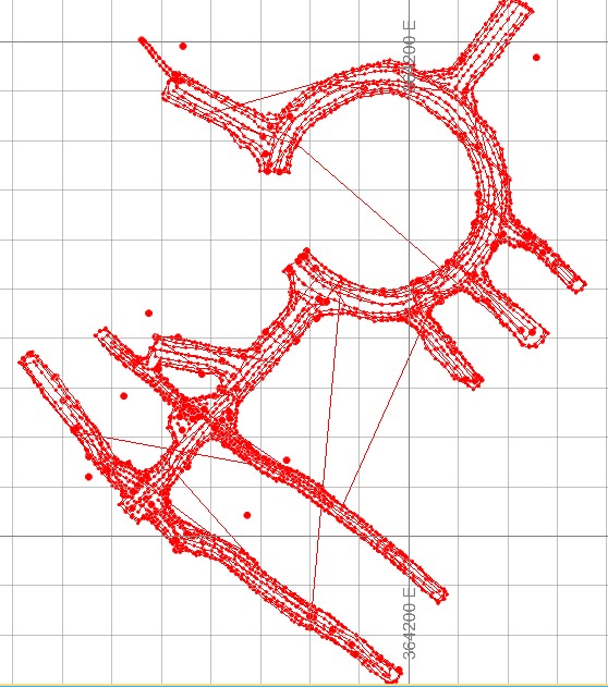
In this case, laser indicators and other structural landmarks aren't needed. These should be attributed and filtered to show only data relevant to solid reconstruction, e.g.:
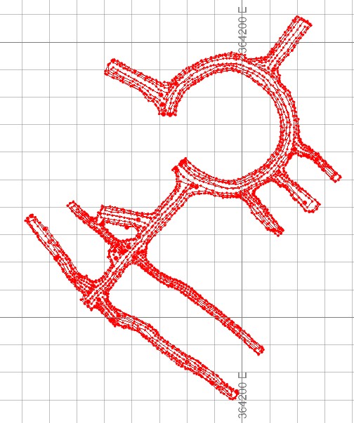
Solid generation then considers only unfiltered data and, as no data has been preselected, everything displayed:
Data Preselection
You can preselect data to construct a drive solid only around selected strings.
This is useful where there are distinct structures in the surveyed string file which would be better constructed independently but added to the same resulting data object.
How is a Solid Constructed?
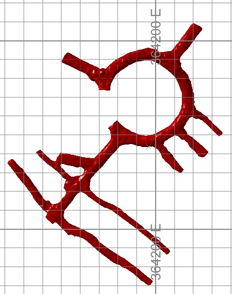
Studio Survey features a unique function that requires only an input string object and, if required, an optional parameter to determine how a data hole is detected. There is no requirement to specify particular landmarks such as roof strings, shoulder outlines, wall outlines or floor outlines; the calculation of a solid is automatic.
Essentially, Studio Survey determines, based on your input string shapes and lengths, what represents the floor, wall and roof of your solid, and if there are any internal voids, where they are.
If your input strings object contains tag strings, they are honoured. This can be an effective way to encourage surface generation along a particular axis.
Wireframe data is generated either as a new object or into any nominated wireframe object. This means you can assemble multiple drive solids within a single object easily, or the opposite.
Hole Detection
Studio Survey analyses your input surveyed string data to assess which closed outline strings represent a development structure outline and which represent internal voids. For example, the surveyed strings below (shown in plan) feature two closed outlines. The larger outline, encapsulating zone 2, is a drive wall outline but the smaller outline around zone 1 is a feature string that represents part of a drive floor and roof:
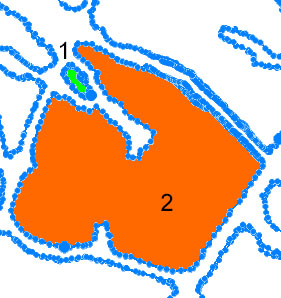
Studio Survey regards outline 2 as a wall, due to its relative length compared to others in the data group. It does this by regarding the Hole threshold (%) value. For a threshold of 50%, meaning a string will only be regarded as a data void if it is 50% or greater in length than its average counterpart, zone 2 easily qualifies as a void.
Zone 1 will become part of the drive solid as its circumference is much shorter than the threshold value. Essentially, higher threshold values tend to produce outputs with more internal voids. Actually, in this case, simply deleting the boundary strings in zone 1 would achieve the same result.
You can also surface data representing two distinct developments; your application will understand data that is in two clearly distinct areas and surface them separately.