
Specify Paint Lines for a Memo Report
Define a laser position, direction and projection distance in relation to a backsight point.
To configure a Paint Lines memo report:
- Open the Memo Reports pane.
- To define the scope and general properties of your report:
- Select the Current Decline, Current Area and Current Level for the report.
Note: these options are created in Database Settings.
- Enter the following fields.
Next memo. Displays the title of the next memo report to be created. Use Format to either select a previously defined prefix or enter your own prefix as required.
Note: manage the number of digits in your memo title suffix by entering zeroes after another Format value. For example, if the format "Memo0000" is specified, memos will be titled using a similar increasing numeric suffix, e.g., "Memo0001", "Memo0002" and so on.
- Description
- Surveyor. Surveyors are defined in Database Settings.
- Report date
- Select the Current Decline, Current Area and Current Level for the report.
- To select 3D data for your report:
- Pick a Surveyed String representing relevant survey data. This string contains drive and development wall strings.
- Pick a Development Design String representing the planned development design for the corresponding reporting period.
Note: 3D survey data is added to your system using the Add to Database task.
- To view your 3D data before reporting:
 Load survey or design string data into the primary 3D window by clicking Load the Data into the Project.
 Preview 3D data using InTouch GO by clicking View the data in the previewer.
- Select the Paint Lines tab.
- Select Pick Design Centreline and pick the design string centerline in the 3D view. The design string is highlighted and the following fields are populated from your design string:
Drive name
Drive height
Drive gradient
Drive profile
You can edit these field values for reporting purposes.Note: for the first selection in a project session only, there may be a short delay between picking the design string and the 3D view and task updating.
- To position and orient your laser:
- Click Create Stop Distance.
- Select any position on the loaded survey string to position your laser. A "BS" (backsight) indicator displays.
- Select a position to indicate the direction and extent of excavation. A "STOP" indicator and a dashed T-junction line displays.
For example: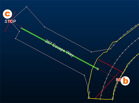
- If a precise Stop distance is required, enter your own value to update the 3D view.
- If required, add additional Comments. These will appear on the generated report. Comments are specific to a report.
- Click Create Report. Dismiss the confirmation prompt when complete.
Note: Reports can take several minutes to complete.
- To view the memo report and associated 3D data:
- Use Results to select the time corresponding to the report to view. All reports run on the Report date are listed.
- Load your memo report results into the primary 3D window using Load the Data into the Project.
- Display selected report media using View the data in the previewer.
Note: pick report media output options in Database Settings.
- Save your project.