
Stope Report
To access this screen:
-
Activate the Survey Reports ribbon and select Stope.
-
Run the command "survey-stope-report"
-
Use the quick keys 'sdr'
The Stope Report tool is used to calculate underground extraction volumes representing a time period. Specifically, these volumes will relate to stope volumes, avoiding any multiple counting of volumes that have already been removed.
This tool allows you to input four key shapes that will be used to determine the overall void created by the stope in question. Optionally, you can also report over break and under break results based on a comparison with a design stope shape.
The following inputs are typical when calculating volumes for an EOM stope report:
-
A Stope Scan Solid: typically a Lidar/CMS derived wireframe (you can find out more about recreating surfaces from scan data here). This is, effectively, the 'ground truth' of what void exists, without considering any previous mining from development operations (in either the upper or lower development areas).
-
A Surveyed Solid for the upper and lower stope regions. These represent the actual upper and lower drive solids. Only the lower solid is required - the upper solid can be specified if need be. These shapes are subtracted from the stope solid where applicable.
-
Optionally, a Stope Design Solid: this is the design shape, typically from Datamine's Mineable Shape Optimizer (MSO) tool, which will also be depleted using any specified surveyed solids. The resulting "design void" will be compared with the stope void in order to calculate stope over break and under break. If no Stope Design Solid is specified, these calculations will not be performed.
-
Optionally, a Block Model to evaluate the contents of the stope volume, such as the tonnage, grade and resource categorization. This will require the specification of a suitable evaluation legend.
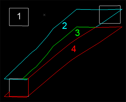
Consider the following example, showing a cross section of a designed stope from MSO (2) and a surveyed stope wireframe (3+4) and upper and lower development survey wireframes (both represented by 1):
...and in 3D...
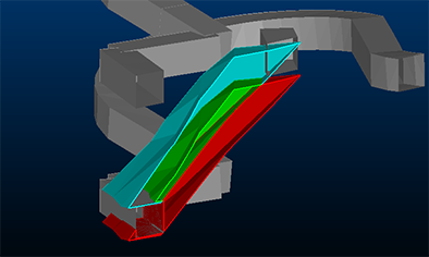
In this case, (3) represents the mined-and-planned volume, (2) represents the planned-not-mined volume and (4) represents the mined-not-planned volume (depleted by the development survey data - 1).
The Stope Report calculates and reports against these volumes automatically, for a given survey date.
Avoiding Multi-counting of Void Volumes
If other stope volumes exist on the same level, they will automatically be considered to avoid any multi-counting of void volumes. For example, if Stope A's excavation intrudes into an area common with Stope B, Stope B's void will not include the volume resulting from Stope A's excavation.
Note: This tool supports batch processing: use Add to Batch to schedule processing at a later date, using the Run Batch task.
Stope Report Contents
This report calculates a stope void volume and, optionally, void volume differences between surveyed and designed stope volumes (mined not planned, planned not mined, mined and planned etc.).
As such, a Stope Reportmay contain the following results:
-
The stope void volume, depleted by any prior stoping and development volumes (e.g. drives)
-
(Optionally) The designed stope volume, if one is specified. This is reported alongside the stope void volume (see above).
-
(Optionally) Evaluation results for the calculated stope void volume. Requires an input block model.
-
(Optionally) The volume outside the model assuming a default density, if selected.
-
(Optionally) Overbreak and Underbreak calculations, by comparing the void volume with a design stope shape.
This information is presented in the form of whichever outputs were selected using the Database Settings panel (Datamine table, Excel report, PDF report, Solids, Plot and/or a file browser).
An output Excel or Plot report require a reporting template to be specified. These templates (.xlsx and .dmtpl respectively) are also specified using the Database Settings dialog.
|
|
You can add stope and development data for a given time period to the current database using the Add to Database utility. |
Using the Reporting Date Calendar
When you select a date for reporting, the calendar tool can be used to see previous report date(s). These are highlighted in red, e.g.:
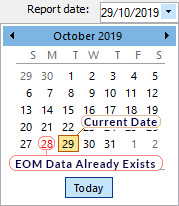
You can regenerate EOM data for any date, including dates for which EOM
output already exists but, in this scenario, you will need to confirm
if you wish to overwrite existing data.
Previewing and Loading Report Data
EOM reporting panels offer functions to preview both your report input surfaces/strings and your output volumes and reports/tables.

- Preview data: available for all report inputs represented by 3D data.
- Load data: available for all report inputs represented by 3D data, including output data.
If results data is previewed, up to three separate displays will be created:
- A PDF or .emf report: this is generated based on the current Plot Template that is associated with your project. Only displayed if it is possible to generate an output report in this format. Not seeing a PDF or .emf report? Check to see if your report has an associated plot template, using the Database Settings screen.
- Wireframe Volume: this represents the cut & fill solids created by your reporting task. This is shown in Datamine's Table Previewer application. Only displayed if it is possible to construct a 3-dimensional volume from the input data of your report.
- A Report Table: this table, in Datamine format, contains the volume assessment of your cut & fill volumes for the selected report. If it is not possible to construct a 3-dimensional volume, a table (nor any other output) will be displayed.
Configure a Stope Report
-
Choose the Current Decline that is relevant to your report.
This is the decline associated with the current underground survey project is set using the Database Settings screen. You can either pick an existing decline using the drop-down list or access the settings dialog to modify the pits of the current database.
-
Choose the Current Area.
This is the underground area for the current report. This can be changed using the Database Settings screen, accessible via the browse button. You can either pick an existing area using the drop-down list or access the settings dialog to modify the areas of the current database.
-
Choose the Current Level.
As above, you can edit the levels of your current database using the Database Settings screen.
-
Choose the Current Stope.
This is the stope that represents the void volume you wish to calculate and report against. using the Declines panel of the Database Settings screen.
-
Select the Surveyor for the current report. Surveyor names are configured using the Survey Database Settings task. The Surveyor is displayed in the output end-of-month results, and will appear in the generated spreadsheet report once published.
-
Choose the Report Date. This is the date to be associated with filing the report. By default, this will be the current date. This information is stored in the output wireframe triangles file generated by the reporting process (according to cut and fill calculations), and will be shown in the accompanying published spreadsheet.
Note: You can generate multiple reports on the same day if you need to; each report will be labelled according to the time it was generated.
-
Choose a Stope Scan Solid. This list contains all previously added stope scan solids. Typically, these wireframes are generated using surface reconstruction routines and based on cavity scan data.
A Stope Scan Solid must be specified if you wish to run a stope survey report.
-
Optionally, define an upper development wireframe (based on survey data) using the Surveyed Solid (Upper) list. This volume will be used to deplete the void volume of the Stope Scan Solid to determine the stope excavation volume. This is an optional field - if you don't want to specify an upper drive, select <None> from the Level dropdown list.
-
A lower surveyed development solid must be specified in order to run a stope report. Pick one from the Surveyed Solid (Lower) list. It will be used to deplete the stope void volume if required.
-
Choose Calculation Options to remove unwanted trivial fragments caused by near adjacent surfaces and the cut and fill calculation process:
-
Remove solids with volume below: by default, all cut and fill volumes that represent the difference between the specified surfaces (optionally constrained by a boundary) will contribute to the output EOM report. You can change this number to remove trivial fragments below a specified volume, with higher values leading to potentially greater volume removal where multiple small volumes are output.
-
Trim solids with thickness below: reduce the number of thin data fragments result from near-coincident surfaces by increasing this value. Higher values will tend to increase the amount of data removed from the output cut and fill solids and resulting report.
-
Decimate input surfaces to limit triangles to: ground data can be represented by very dense wireframe data, and this can lead to increased cut and fill calculation times. Enabled by default, input surfaces will be pre-decimated to reduce their data density and commit less dense/simplified data into the EOM volume calculation routine. This can increase the performance of the EOM reporting tool at the sacrifice of input surface detail.
-
-
Optionally, Use a fixed plot scale.
-
If checked, you can enter a custom scaling ratio in the activated field. The output PDF report will honour the custom scale, and if any Plot title boxes include a scale report, it is automatically adjusted to show the custom value used.
-
If unchecked, a scale is automatically calculated based on the output EOM data and Plot projection dimensions.
-
-
To generate evaluation results as part of your report, one option is to specify a block model:
-
Enable Use block model for reporting.
-
Use the "..." button to display the Block Model Options popup.
-
Fill out the fields on the Block Model Options screen and click OK.
Alternatively, instead of deriving a density from the block model database for purpose of tonnes/grades reporting, you can specify a default Density instead.
Note: You can either choose to generate evaluation results using a block model or a default density, not both.
-
-
Create Report: you can generate a report providing you have completed the following tasks on this screen:
-
Set up your data context (decline, area, level, stope, surveyor, date)
-
Selected a Stope Scan Solid.
-
Selected a Surveyed Solid (upper) if you require on - this is optional.
-
Selected a Surveyed Solid (lower)
-
If underbreak and overbreak reporting are needed, selected a Stope Design Solid.
-
Defined appropriate wireframe output cleaning options
-
Defined a block model if you want void volume evaluation results.
Your output 'report' includes the elements specified on the Database Settings screen (for the Development Report section). You can view the output data using the tools in the Results section (see below)
-
-
If you intend to run a Stope Report as part of a batch operation, select Add to Batch. It then appears on the Run Batch screen.
-
Review your Results.
For each report run, a list item displays, labelled according to the time it was generated. The current list of reports represents the reports created on the current Report date.
You can preview the results of the report (this can display a variety of things, depending on your current Database Settings(Preview options), for example, you may be able to show a Datamine table, a corresponding PDF report, based on the current report template) and/or other options. Each report can be set up independently with regards to what data is shown when you preview results.
You can also load the results of the excavation calculation. This button is only enabled if the selected item contains 3D data (i.e. data generation has been successful).
Related topics and activities