
Strings Properties: Symbols
To access this screen:
-
Display the Strings Properties screen and select the Symbols tab.
Use the String Properties: Symbols screen to add 2D or 3D symbols to each string vertex and configure their size, rotation and colour. Changes made on this screen affect the target 3D overlay only.
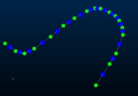
As with other Symbols screens, you can define one or more configurations. Multiple configurations permit the display of multiple symbol groups on the target data. All formatting options relate to the currently selected symbol group only. So, for example, you want a string to have a green circle symbol at each vertex position, but a blue diamond at the centre position of each edge, pointing along the line like this:
To configure the symbol used to represent a point or string vertex in the 3D window (for the selected overlay):
-
Load or create 3D data to format. Make sure it is visible in a 3D window.
-
Display the Symbols screen.
-
Check Display symbols. If unchecked, symbols are not displayed and can't be configured.
-
Choose the Type of symbol to use:
-
2D – A two-dimensional (flat) symbol that is always displayed orthogonally to the view. This symbol can be rotated whilst honouring this orientation, but can't be adjusted in any other plane. A 2D symbol is represented by a bitmap graphic using Legend Controls.
-
3D – A three-dimensional symbol that can be rotated around any axis. These symbols are always scaled according to the current 3D world magnification. Choose from either:
-
Default box – A default cuboid shape appears at each point position.
-
Imported model – Show a .x (ActiveX) format 3D object at each symbol position. These 3D shapes can be oriented using Rotation controls (see below) around any major axis.
-
-
-
Define Size options for the symbol using attribute values, or leave <none> selected, meaning object data values aren't considered when sizing symbols.
-
Legend – Pick the legend that matches attribute values to a size
Note: A filter legend can also be used to define the size of symbols without the requirement to select a column. If a filter legend is selected, then the column dropdown list is not available. Filter legends use logical expressions to denote the various legend intervals. The difference between this and the other legend types is that a legend interval is explicitly defined (for example, “AU>=3 AND AU< 10”).
-
Column – Pick the data column containing the numeric size values.
-
-
Define Constraints for the base size value by specifying a Minimum and Maximum size.The constrained values are then multiplied by the value in the Scale box to produce the final size.
-
Set a Scale factor, and specify whether the size of symbols refers to their size 'on-screen' or in 'world-space'.
Note: The 'size' of a symbol refers to its longest dimension.
Sizes can be defined in terms of screen pixels, by selecting Screen in the Scale group (2D symbols only). This setting provides a fixed, 'on-screen' size. Symbols can also be defined in world coordinates by selecting World. This setting allows size to be specified in the virtual world, and results in their size varying according to their distance from the 3D viewpoint in 'world-space'.
-
(String overlays only) Use Size adjustments to differentiate between the first and other vertices of a string, and to optionally change the scale of symbols only on selected data.
-
First symbol – you can either leave the point at the default size (No adjustment), Scale it by a factor, or Set it to a specific size.
-
Selected strings – change the symbol size for selected strings using the same options as above. This can help to highlight selected string data in a busy 3D scene.
-
-
(String overlays only) Use Position settings to define where symbols appear along the target string overlay.
-
Every – Show symbols at the vertex (Point) position or the mid point position on each string Edge.
-
% along – If you want to position symbols on a string edge, but need more control over precisely where, choose this option and at which part of the edge you want them to appear.
-
Intervals – If the spacing of symbols is important, set the distance between symbols along the string. This could be useful, for example, to create a type of tape measure in 3D.
-
-
Use Rotation settings to orient your symbol in either 2D or 3D space.
-
Fixed rotation (an azimuth around the view plane) is only available for 2D symbols. Enter a rotation value in degrees to orient all symbols by the same amount for the target overlay.
-
Dip / Dip direction / Roll can be set to orient a 3D symbol around any major axis in relation to the current Plane.
-
Draw in 2D - Only available for 2D symbols. If selected, then the symbols are displayed in the plane of the screen, but still orientated in the direction that you have specified. If Dipis selected and the Draw in 2D option is not selected, then only World is available in the Scale list.
-
-
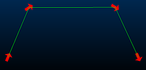
(String overlays only) Point between lines: if selected, then the symbol is positioned on each point, and is orientated as follows:
-
At the ends of an open string, it is orientated in the direction of the string segment.
-
On the vertex between two string segments, it is oriented half way between them, as shown below:
-
-
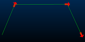
(String overlays only) Point along lines: if selected, the symbol is positioned on the vertex at the end of each string segment, and is aligned in the direction of the string, as shown below:
-
-
Define the Color of symbols using Legend Controls.
Related topics and activities