|
|
Extruding a profile along a design string |

Create Drive
To access this dialog:
Extrude a designed profile shape along one or more design strings. You can either use a preset shape or set up a custom outline by defining the positions of the outline vertices.
A profile object is used to store the details of your profile; this data is transferrable to other projects and systems using an XML format file. Profile data is not stored in memory as a 3D object and, as such, is only accessible (and editable) using the Create Drive dialog.
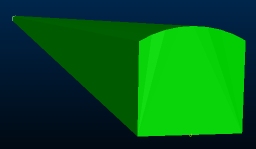
This command would be used to construct a 3-dimension volume by extruding a profile shape along one or more design strings, typically representing an underground drive layout, although it can be used to extrude a profile shape along a design string for any purpose.
The output volume is closed (i.e. end-capped) and stored as a wireframe object that can be accessed using other structural tools in your application.
Field Details:
The Create Drive dialog contains the following fields:
Profile: a drop-down list containing all profile shapes associated with the current project. These items are not accessible as standard 3D objects (instead, they are defined as transferrable XML data). You can select an existing profile to modify, or you can Add a new shape (see below). If nothing is selected in this list, a new profile shape will be automatically created.
Import: import a profile shape XML file containing profile information.
Export: export all current profile definitions as a portable XML file. All profile shapes will be represented by the output file.
Add: create a new profile shape with a default "NewShape" Name. A default regular square profile will be defined automatically for the new shape, but can be edited (as can the Name - see below).
Copy: create a copy of the current profile and add it to the bottom of the Profile drop-down list.
Delete: remove the currently selected Profile from the project.
Name: the name of the current profile. Editable field.
Profile Type: you can choose a preset shape (which can be scaled) or you can define each vertex of the outline independently. You can choose from:
-
[Pointlist] - a shape based on a freeform list of vertex positions. This option lets you edit the X or Y positions of any vertex within the profile shape.
-
[Rectangle] - a shape with an editable Width and Height.
-
[Circle] - a circle with an editable Diameter.
-
[Arch] - a shape defined by its Width, Height and Arch Radius. For example:
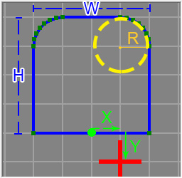
Where:
- H and W represent the configurable Height and Width.
- R represents the turning radius of the arch curves
- X and Y represent the offset from the default intersection point (the 0,0 origin or the 2D shape). In this case Offset X = 1 and Offset Y = -1 (see below).
|
|
If defining a square or arch profile, you can also automatically resize map profiles when adding them, adjusting the height and width automatically. More about map profiles... |
Coordinates Table: all profile coordinates are shown in a local system, with the origin represented by the red cross (+). Coordinate values are automatically calculated (and therefore locked) for the [Rectangle], [Circle] and [Arch] Profile Types (see above).
If a [Pointlist] Profile Type is selected, the coordinates table is editable. You can enter positive or negative numeric values into the table, which will update the preview graphic below. All coordinates are local to the origin of the profile, represented by a red cross. This is the point through which your design string will pass if no offset values are specified (see below).
Profile Preview Graphic: this section of the panel represents a preview of the profile shape you are creating. Depending on the Profile Type that has been selected, different editing options become available (see above).
Offset X/Y:
enter positive or negative values to change the intersection point of
the profile shape with the selected design string(s). Regardless of these
settings, the 0,0 origin of the 2D shape will not change (i.e. it will
be fixed at the default origin even if you offset the intersection point).
For example, in the image below, the graphic preview has been superimposed
onto the generated wireframe:
Floor Plane: set the orientation
of the base of the profile shape by choosing one of the following options:
-
Horizontal
-
East-West
-
North-South
-
West-East
-
South-North
For example; the following image shows how the same
profile shape can be used to extrude two drive shape in relation to a
design string. The only difference is that the drive on the right was
generated using an [East-West] Floor
Plane and the drive on the left using a [West-East] Floor
Plane. The design string is oriented in a North-South alignment: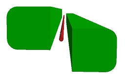
Link Selected Strings: apply the current profile to all selected string data. Data can be preselected within the same string object or different string objects. All selected items will be used as a basis for drive creation.
Close: close the Create Drive panel without further actions.
|
|
Related Topics |
|
|
create-drive |