|
|
Command Help |
|
Command Name |
Menu |
Quick Key |
Link to Command Table |
|
link-drive-in-segments |
Command line only |
lds |
|
|
This command is only supported in the legacy Design window. |
Description
Link drives using rules based on simple geometric shapes.
How to Use
-
Select the drive string.
-
Run the command.
-
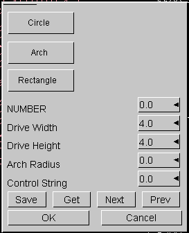
In the Link Drive cross-section dialog (is displayed if no Drive Cross-Section file is currently open), define settings, click OK:

This dialog is used to define the shape of the cross-sections along the drive, and contains the following fields:
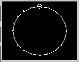
Circle: create a circular cross-section template, e.g.:
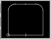
Arch: create an arched cross-section, e.g.:
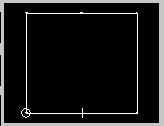
Rectangle: create a rectangular cross section, e.g.:
The following modification commands are available:
Number: the number of the current cross-section being defined.
Drive Width: specify the width of the current drive section. Note that the image preview will update to show any changes in aspect ratio.
Drive Height: specify the height of the current drive section. Note that the image preview will update to show any changes in aspect ratio.
Arch Radius: automatically enables the Arch section type. This setting defines the arch used to create the 'roof' of the arch.
Control String: the number of the control string, calculated from current file coordinates.
The following buttons are available:
Save: if there is no link drive cross-section file active, this button displays the Project Browser. You can then enter a filename and click OK. All future changes will be updated in the created/selected file.
Get: load a previously saved cross-section file via the Project Browser.
Next: if more than one section has been defined in the current set, and the last section in sequence is not active, this will update the panel to show the next section details in sequence.
Prev: move to the previous section in sequence. -
In the Project Browser, select the Drive Statistics file, click OK.
-
In the Drive Density dialog, define the Density for the drive material, click OK.
|
|
Using this command in conjunction with the 3D Solid linking method. If you have strings on adjacent sections that are to be linked together, and those strings cross each other when viewed in the direction of wireframing, then temporary vertices are inserted into the string and these temporary vertice are used when the wireframe is created. Since pairs of strings are wireframed at a time it is possible for these temporary vertices to be created for one pair of strings and not the other. In this situation a wireframe may be built which contains inconsistencies. Therefore the 3D-Solid method is not suitable for use with the older linking commands if adjacent sections contain strings that cross each other in the direction of wireframing. |
|
|
Related Topics |
|
|

