|
|
Command Help |

|
Command Name |
Menu |
Quick Key |
Link to Command Table |
|
grid-dtms |
Solids ribbon | Operations | DTMs | Grid DTMs |
grd |
Description
Create a grid of points to represent the average, minimum or maximum elevations of points belonging to multiple (and potentially overlapping) wireframe surfaces.
How to Use
-
Ensure at least one wireframe object exists in memory.
-
Run this command.
-
The Grid DTMs dialog is displayed.
-
To output the points to the current point object, choose the Current Object option. Otherwise, choose the New Object option, and add the name to the edit box.
-
The Grid Increment specifies the grid point spacing in the X and Y axes. Points will only be created where they lie over an included surface.
-
Where there are overlapping surfaces, both within a single wireframe, and/or between multiple wireframes, the Combine Elevations option chooses how the sample point elevation will be calculated. This can either be the minimum elevation encountered, the maximum elevation, or an average of all the elevations encountered.
-
The wireframe objects to be used to generate the point grid can be selected within the Objects list. These can either be selected by ticking the box next to the required wireframe name, or by using the pick arrow button, and then clicking on the wireframe in the Design view. All objects can be selected buy using the All button, and all selections can be cleared by using the None button.
-
Select OK to start the conversion, or Cancel to cancel.
|
|
In conjunction with make-the-dtm, The grid-dtms command can be used as alternative to the boolean command Update DTM (Wireframes | Boolean Operations | Update DTM), providing more options as to how the surfaces are combined. However, since the grid representation may be quite dense, large triangle count wireframe surfaces may result, so it may be advisable to decimate the final wireframes. |
Example
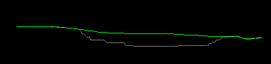
In the image below, two wireframe intersections are shown overlaid in a vertical section, representing an unmined topography (green) and open pit profile (grey).
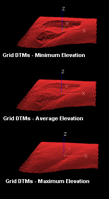
The following image represents the matrix of points generated when the Combine Elevations option is set to Minimum, Average and Maximum respectively. In this example, a grid increment of '10' was used to prevent the generation of a large density of grid points:
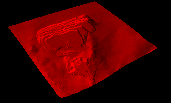
These grid points can further used to generate a wireframe surface using the SURTRI process (either from the command line, or via Wireframes | Wireframing Processes | Create DTM. The resulting wireframe can then be used in other processes as required. Please note that the resultant surface will appear 'smoother', but may have lost some of the original definition present in the original wireframe surface.
|
|
Related Topics |
|
|
make-the-dtm |