SLIPER Process
To access this process:
- Enter "SLIPER" into the Command Line and press <ENTER>.
- View the Find Command screen, select SLIPER and click Run.
See this process in the Command Table.
Process Overview
Intersects a set of parallel perimeters by a set of orthogonal planes.
This process produces two optional output files:
-
An intersection file, containing the co-ordinates of the end points of the line describing the intersection of each plane and the perimeters.
-
A perimeter file, connecting the co-ordinates of the intersections in the form of a standard perimeter.
The input perimeters may be parallel to any one of the three co-ordinate axes, and the intersection plane will be perpendicular to the input perimeter.
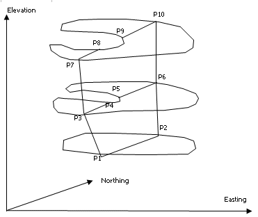
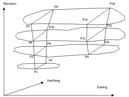
For example, Figure 1 shows a set on input perimeters representing the plan outline of a particular rock type on 4 benches. These perimeters are intersected by 2 north-south planes. The output intersections file contains 7 fields - the X, Y and Z co-ordinates of the 2 end points (X1, Y1, Z1 and X2, Y2, Z2) and a perimeter value field containing the PVALUE of the original perimeter. In the example of Figure 1 the file will contain 7 records, one for each of the intersection lines P1P2, P3P4, .... P13P14. The X1 and X2 values are northings, Y1 and Y2 the elevations, and Z1 and Z2 the easting of the intersection plane. The PVALUE for intersection line P1P2 is 10.
The intersection lines for any intersection plane can be plotted by using the PLOTLN process under the retrieval criteria that ZP is equal to the section co-ordinate . In this example the retrieval criteria would be for the easting (ZP) value. Each intersection line can be annotated with the original PVALUE using the PLOTAN process. In this way it is possible for the input perimeter file to contain several perimeters for each bench, representing different rock types, with the PVALUE field containing a rocktype identifier. Using PLOTLN as described above it would be possible to distinguish between intersection lines for the different rock types.
The output perimeter file is a standard perimeter containing fields XP, YP, ZP, PTN and PVALUE. In the example of Figure 2, the output perimeter file would contain two perimeters. The first perimeter would have eight points ordered P1, P3, P5, P7, P8, P6, P4, P2 and with both ZP and PVALUE equal to the section easting. If the input perimeter contains a re-entrant, or there are multiple perimeters on a single bench, then the output perimeter will describe the outermost points of the intersections of any line.
Note: There is a limit of 1200 points in any single input or output perimeter, and a limit of 20 intersection lines, for the intersection of a single perimeter plane and an intersection plane.
Input Files
|
Name |
Description |
I/O Status |
Required |
Type |
|
PERIMIN |
Input perimeter file containing at least 2 perimeters. This must contain the fields[XP,YP,ZP,PTN,PVALUE, all numeric and explicit] with XP and YP variable and ZP fixed for each perimeter. The file must contain at least two perimeters with different ZP values. |
Input |
Yes |
String |
Output Files
|
Name |
I/O Status |
Required |
Type |
Description |
|
INTERSEC |
Output |
No |
Undefined |
An optional output intersections file containing the coordinates X1,Y1,Z1 of the end points of each intersection line, and the PVALUE of the intersected perimeter. At least 1 output file must be specified. |
|
PERIMOUT |
Output |
No |
String |
An optional output perimeter file containing the intersection perimeters. At least 1 output file must be specified. |
Parameters
|
Name |
Description |
Required |
Default |
Range |
Values |
||||||||||||||
|
MODE |
|
Yes |
1 |
1,6 |
1,2,3,4,5,6 |
||||||||||||||
|
STARTPOS |
Starting position for intersection planes. |
Yes |
Undefined |
Undefined |
Undefined |
||||||||||||||
|
STIZE |
Interval between intersection planes. |
Yes |
Undefined |
Undefined |
Undefined |
||||||||||||||
|
NUMST |
Number of intersection planes. |
Yes |
Undefined |
Undefined |
Undefined |
||||||||||||||
|
CLOSE |
Close perimeters, either 1 to close or 0 to not close. |
No |
1 |
0,1 |
0,1 |
Example


Error and Warning Messages
|
Message |
Description |
| 130,n,F,SLIPER |
Input &PERIMIN file not specified. Define an &PERIMIN file. |
| 131,n,F,SLIPER |
Neither output file specified. |
| 132,n,F,SLIPER |
Input &PERIMIN file does not exist. Check that the specified &PERIMIN file exists and has been added to the project.. |
| 134,n,F,SLIPER |
One or more of the compulsory fields XP, YP, ZP, PTN, or PVALUE are missing from the &PERIMIN file. Check that the fields exist in the &PERIMIN file. |
| 138,n,F,SLIPER |
The number of points in one of the input perimeters exceeds the maximum of n. Condition the &PERIMIN file and reduce the number of points per string. |
| 139,n,F,SLIPER |
One of the input perimeters is not sorted on the PTN field. Sort the &PERIMIN file on the fields PVALUE and PTN |
| 140,n,F,SLIPER |
Error when reading &PERIMIN file. Check the contents of the &PERIMIN file. |
|
141,n,F,SLIPER |
@MODE parameter not specified. Select a @MODE parameter value. |
| 142,n,F,SLIPER |
@MODE parameter not in range of 1 to 6. Select a @MODE parameter value of 1, 2, 3, 4, 5, or 6. |
| 143,n,F,SLIPER |
@STARTPOS parameter not specified. Select a @STARTPOS parameter value. |
| 144,n,F,SLIPER |
@STIZE parameter not specified. Select a @STIZE parameter value. |
| 145,n,F,SLIPER |
@NUMST parameter not specified. Select a @NUMST parameter value. |
Related topics and activities

