
Interactive Ramp Tool
To access this screen:
-
Digitize ribbon >> Design >> Interactive Ramp.
The Interactive Ramp Tool provides an interactive environment for creating ramp designs specifically for underground projects. In this environment, you are the optimizer, while the tool provides real-time metrics and visual indicators to help you produce solutions that honour the constraints that you have specified. To use the tool, fill in the Global Parameters then activate the Interactive Mode.
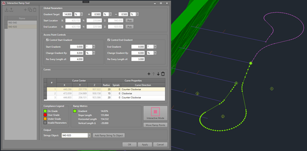
The Interactive Ramp Tool in Studio UG
The ramp string is only displayed in the 3D view whilst Interactive Mode is active. When you are happy with the selected ramp design, specify an existing object or a name for a new one, then click Add Ramp String To Object to save it and deactivate the Interactive Mode.
Note: You can save all the ramp parameters specified on this panel - to return to a previously designed ramp and make further adjustments, activate the Interactive Mode again.
Warning: You must click OK or Apply to save ramp definitions (all the settings pertaining to the ramps that you have created or modified). The actual output strings are not joined to the definitions seen in the tool window.
Note: This screen includes table grids that support multiple row selection.
Managing Ramps
To configure ramps, set up a definition on the left of the panel, then assemble the elements of the corresponding ramp condition on the right.
The left side of the Interactive Ramp Tool panel can be used for the following functions:

-
Import an XML file containing ramp definitions.
-
Export the currently-defined ramps as a portable XML file. This can be transferred to other systems, for example.
-
Add a new ramp to the collection.
-
Copy the currently selected ramp to a new item.
-
Delete the currently selected ramp.
Global Parameters
These settings apply to the whole ramp and are generally specified first.
-
Gradient Target – The desired gradient to be achieved for the ramp design. The value can be related to any of the following units: Percentage %, Degrees ⁰ or Ratio 1:n.
-
Plus (+) and Minus (-) – The acceptable deviance limit values based on the Gradient Target (see above). This affords some play with respect to the acceptability of the solution while interacting with it in the 3D window (see: Compliance Legend). For example, with a Gradient Target of 12% and a +/- limit of 0.5%, you are defining that your ramp gradient is acceptable for any value between 11.5% to 12.5%. The +/-limit values can be related to any of the following units: Percentage %, Degrees ⁰ or Ratio 1:n.
-
Start and End Locations – The start and end points for the ramp design. These points are defined interactively by clicking Pick and selection the desired position on the 3D view. The current Snapping mode is honoured if picking points. You can also enter coordinates directly into the Start Location and End Location coordinate fields if you wish.
-
Alternatively, to adjust the start and end points by coordinate values, rather than digitization through the pick buttons, enable Interactive Mode (see below) and use the edit-point-coordinates (quick-key: "epc") command to select the start or end grips in the primary 3D window.
Access Point Controls
These options allow you to specify gradient transitions at the start and end of your ramp. A transition consists of an initial gradient (start or end), gradient change between segments, segment length and the target gradient as specified in Global Parameters.
You can choose to activate or deactivate these options at any time.
-
Start/End Gradient – The gradient for the first/last length segment of the ramp. The value can be related to any of the following units: Percentage %, Degrees ⁰ or Ratio 1:n
For example, if you define a Start/End Gradient of 2% and a segment length of 6 meters on the Per Every Length of field, it means that for the first and last 6 meters of your ramp the gradient will be exactly 2% (absolute).
-
Change Gradient By – The maximum allowed gradient change until it reaches the Gradient Target value. The value can be related to any of the following units: Percentage %, Degrees ⁰ or Ratio 1:n.
-
Per Every Length of – The segment length (in meters) that incremental gradient changes are applied for the ramp Start and End control regions.
For example, if you define an Initial Gradient of 2% and allow the tool to Change Gradient By 4% Per Every Length of 6 meters, you will create:
-
A ramp with a gradient of 2% for the first 6 meters.
-
With a maximum change of 4%, the next 6 meters of the ramp will have a gradient of 6%, the following 6 meters a gradient of 10% and the following 6 meters a gradient of 12% since this was the defined Gradient Target.
-
After the Start/End region reaches the same gradient defined as the Gradient Target, the gradient is a result from the ramp length and vertical distance between start and end points.
Warning: In some cases, the transitions cannot be applied. This is likely due to there being insufficient horizontal ramp length to accommodate the start or end transitions. You can either adjust the transition parameters, or, while in Interactive Mode, add some length to your ramp until the transitions appear – this indicates to you the length needed to accommodate them.
Curves
To control the ramp shape, add Curves and control their position along the 3D view. The ramp gradient is controlled by the Start and End point together with the Curves positions, being a result of vertical difference and length.

The Curves table is where you add a curve profile and control its parameters, such as Radius, number of Spirals and Direction, but the Curve position is controlled interactively using the 3D view.
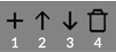
To manage your curves, use the buttons at the top of the table:
-
Add to add a curve profile
-
Move Up to move a curve profile up the list. This changes the order in which the curve will be visited by the ramp path going from start to end.
-
Move Down to move a curve profile down the list. This changes the order in which the curve will be visited by the ramp path going from start to end.
-
Delete to delete a curve profile
When adding a new curve to your ramp, only the horizontal position of the specified position is considered; the curve's vertical position is automatically determined.
The new location for the curve must be specified on, or either side of, a straight section of the ramp.
When digitizing a location with Left-Click, the position is as the mouse position intersects the active section plane, if this plane is far away from your design, you may be attempting to insert a curve either very far away, or at an invalid position relative to the ramp. Turn the active section on in the sheets bar to see where your plane is located, and move as necessary with“Edit Interactively on the View ribbon. Otherwise, it is best to use Right-Click (with snapping to lines of strings) to specify a position for the new curve, and then move that curve to the desired position using the Move Ramp Points button
The Curve Properties allow you to control each curve shape:
-
Radius – The radius (in meters) for the ramp.
-
Spirals – The number of complete laps that the curve must follow.
-
Curve Direction – The direction (clockwise or counter-clockwise) the ramp path must follow around the curve.
Moving Curves
To move curves in the 3D view you need to activate Interactive Mode and click Move Ramp Points. After this it is possible to drag and drop any curve to a new position.

- Interactive Mode deactivated
- Move ramp points deactivated

- Interactive Mode activated
- Move ramp points activated
Compliance Legend
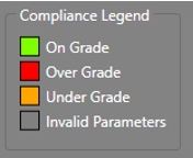
The Gradient metric in the Ramp Metrics section, as well as the Interactive Ramp string while in Interactive Mode, are colour coded according to the following legend:
-
On Grade is when your ramp is displayed in green colour and results in a gradient value that is inside the Gradient Target plus/minus acceptable deviations, meaning that you were able to define the shortest path possible considering all your inputs.
-
Over Grade is when your ramp is displayed in red colour and results in a gradient value that is higher than the defined Gradient Target plus acceptable deviation, meaning that you are creating a design that is steeper than desired.
-
Under Grade is when your ramp is displayed in orange colour and results in a gradient value that is lower than the defined Gradient Target minus acceptable deviation, meaning that you are creating a design that is longer than desired.
-
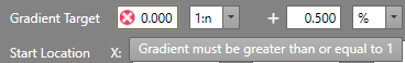
Invalid Parameters is when your ramp is displayed in grey colour. This occurs under two conditions:
-
Invalid inputs – You have inputs (marked with a red and white X icon) that contain empty or illegal values. Hover your mouse over these icons and observe the tooltip describing the problem. For example:
-
No solution – You have a degenerate case where a ramp curve is too close to the start point, end point or a neighbouring curve of opposing directionality. For example:

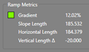
Ramp Metrics
This area provides useful information about the ramp current state.


-
Gradient is the ramp gradient* and it is coloured according to the compliance legend as evaluated against values defined on the Gradient Target and Plus/Minus deviance. The colour of the ramp string in Interactive Mode is also the same.
Note: This gradient refers to the uniformly graded section of the ramp between either the start location, or end of the start transition, and either the end location or end of the end transition. Depending on which access point controls (transitions) are enabled and specified.
-
Slope Length is the total ramp length (in meters)
-
Horizontal Length is the length of the ramp´s horizontal projection (in meters)
-
Vertical Length ∆ is the vertical distance (in meters) from the selected Start and End points
If there are invalid input parameters, or if a ramp path solution does not exist, then these values are displayed as Indeterminate. In this case, check that there are no invalid inputs on the Interactive Ramp Tool window, then, in Interactive Mode (which is only available if inputs are valid), verify that you do not have ramp curves too close to the start point, end point, or neighbouring curves of opposing directionality. (See example under compliance legend).
Output
When satisfied with your ramp solution, you can produce the final ramp string in any strings object you like. You can do this multiple times, in as many strings objects as you like – use the following inputs:

-
Strings Object – Select an existing strings object from the drop-down menu, or type in a suitable name for a new one to be created automatically for your ramp string to be created in.
-
Add Ramp String To Object – Click on this icon to add your ramp design to the selected String object (or the new one to be created automatically).
Warning: This does not save your ramp definitions, You must click OK or Apply to save all modified and created ramps since opening the Interactive Ramp Tool.
Related topics and activities