|
|
Studio UG Tutorial - Dependencies Set up automatic dependency rules for your project |
Underground Planning Tutorial - Dependencies
In an underground planning sense, dependencies describe relationships between activity points (and their corresponding volumes).
By default, activities that have been generated along a design string, or within a segmented extruded solid, will already be dependent on the previous/next activity in the direction of the underlying string.
In Studio UG, dependencies can be described interactively (by selecting predecessor and successor activities in the 3D window) and/or by setting up rules that automatically form dependencies between activities if they fall within a given 'search geometry'. These geometries are ellipsoids that you can (and will, below) define yourself.
For example, you may want to specify that all activities
relating to access drives to levels from the main decline structure
are always constructed in the order of decline access - level access
(completing the former before the latter begins). For example:
This can be done manually, but your decline has to access multiple levels and setting these end-start activity relationships manually would take some time.
Thankfully, dependency rules let you apply the dependencies between activities of the same type, providing the successor falls within a given distance of the predecessor at nominated points. To start with, all activities are set to the <Internal> dependency layer. In this section, you'll change this so that all activities are defined using a series of logical rules that denote what happens before what.
If no dependencies are defined for your project, each design item (as per its definition) will start simultaneously, meaning ore development and stope excavation activities would start before the relevant access drives and shafts have been developed, for example. The resulting schedule would be nonsensical. Dependencies order mining activities into a practical, realistic schedule, based on genuine operational constraints.
In the following exercises, you will:
-
set up dependency layers to control display formatting
-
define a dependency rule set that will connect level access, decline access and ventilation development automatically
-
load the remaining rules (governing dependencies between decline, ore drive and stoping/backfilling activities) into your project from XML
-
set up a manual dependency that deliberately creates an impossible schedule
-
fix the introduced issue using the Dependency Loop detection function.
Dependencies can be defined spatially (meaning their proximity will determine if they are co-dependent) or based on the values of given attributes (e.g. all stopes will be dependent on each other according to their STOPEID value, in ascending order). For this scenario, you will use spatial rules to define your dependencies.
Studio UG considers activity dependencies to be non-negotiable; they must be honoured in order to provide a schedule. If such dependencies prohibit the generation of a schedule, warning and error information will appear in the generated report.
This section may take a bit longer than the others to complete: it can be completed in approximately 30 minutes.
Prerequisites
-
You have completed the previous section (Process Solids).
-
Some familiarity with the Sheets control bar's overlay display settings is assumed.
-
Some familiarity with the Points Properties dialog is assumed.
-
Some familiarity with the Quick Filters control bar is assumed.
Exercises in this section
This section contains the following exercises:
- Set up Dependency Layers
- Set up Dependency Rules
- Define Search Ellipsoid
- Import the Remaining Rules
- Generate Dependencies - First Run
- Sabotage your Dependencies Manually
Exercise 1: Set up Dependency Layers
You can use the Dependency Layers dialog to implement 'layers' of dependencies within the same project.
Different layers can be created for different categories of dependencies in order to make it easier to identify specific types of links during the sequencing and scheduling process. The layer information will also be transferred to the EPS schedule file where it can be used to create additional filters
This is particularly useful if you wish to create, and then apply, different dependency default settings without having to create projects or minor projects. Say, for example, you wanted to create a specific set of dependencies when progressing your underground development from one stope to another, which may differ from the dependencies implicit with the task to progress drive development away from a decline. Layers can be used to independently define a distinct category of dependencies.
Layers can be independently activated/deactivated, hidden/shown, and colored. Each can also be configured to include a custom relationship between predecessor and successor activities (start-finish, finish-finish, etc.). Activity delays can also be set independently for each layer.
- Activate the Planning ribbon and select Dependencies.
- Click Edit
Layers:
- The Dependency
Layers panel is displayed.
All dependencies are assigned to a default layer. You're going retain this layer, but set up two additional layers; one for development and one for stoping. When you define some rules (in the next exercise), you assign the generated dependencies to one of these layers. For this project, layers will assist with visual formatting only, although they could just as easily define the scheduling constraint and, if required, any delay/lag between activities of each layer. - Click the "+" icon in the top right corner to add a new row to the Dependency Layers table:
- Edit the Name of the layer to "Development" and change the Colour to [54] (light pink).
- The Default Type (meaning: the default scheduling constraint for dependencies assigned to the layer) is fine: you want predecessor activities to be completed before the successor activity begins.
- There will be no lag between your activities, so the Default Lag columns can be left as they are.
- Note the Count values: currently, your project has no dependencies, so the [Default Layer] and [Development] items read zero. When you generate activities (using rules) later, these numbers will change.
- Create another layer called "Stopes"
and set the colour to [57]. This will be used to contain stoping
dependencies.
You should now be looking at the following table: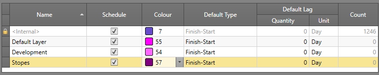
- Click OK to close the Dependency Layers panel.
Exercise 2: Set up Dependency Rules
In the following exercise, you will define a set of rules that determine how activities are connected between decline and level access structures. Following that, you'll import the remaining dependencies from an XML file. These imported dependencies will govern how co-dependent activities will be linked between:
- Decline and ventilation shaft activities.
- Level and ore development drive activities.
- Stoping and backfilling activities.
In each case, the scope of data that analyzed for automatic dependency assignment will be governed by a predefined filter. These already exist in your project (you used some of them to define your activity naming conventions in a previous section and imported others that weren't used - until now).
Each "rule" can contain one or more instructions. For your project, there will be four 'rules' covering decline, level, ore drive and stoping activities, each containing multiple instructions.
- Using the Dependencies
panel, click Edit Rules:
- The Edit Dependency Rules table is displayed. You are going to use the Spatial Based Rules tab as all of your rules are dependent on an activity's proximity to another in 3D space (meaning activities that are sufficiently close together and pass the defined filters will become dependent).
- Consider the following logic:
- You want your decline access drives to complete before you start the level access drives.
- A level access drive must be complete before any services cubby can be constructed on it.
- A level access drive must be complete before any sump development can start.
- A level access drive must be complete before it can be connected to an extended ventilation inbound and exhaust shaft.
- Ventilation access drives must be completed before ventilation raises.
- A level access drive can't be started until the primary decline has reached sufficient depth.
- A ventilation access shaft cannot be extended until the higher shaft development is complete.
- The logic above represents non-negotiable rules that must be
honoured in order to determine your optimal schedule. Defining
a rule set for the above involves defining the predecessor and
successor activities and how they relate to each other in a spatial
context.
Before you can define this logic as a rule set, you need to define its name; click the "+" button on the left of the screen. - Edit the "NewRuleSet" description to read "LEVEL"
and leave the Use check
box enabled (you can switch rule sets on and off with this check
box - useful for testing the impact of new rules).

- The table on the right is automatically populated with a rule,
using default values.
The first rule of the set governs the relationship between decline access structures and level access structures. It is designed to ensure the level access can't start until the decline access is complete.
All design data that represents decline access development is represented by a filter that was imported in an earlier section (DECL_ACC). Here's a reminder of the filter definition: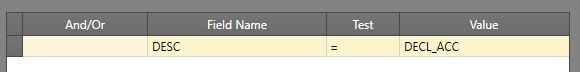
So, in essence, the filter is "any data where DESC is "DECL_ACC" will pass the filter. For reference, your project data contains the following decline access items (highlighted as thicker yellow strings, below):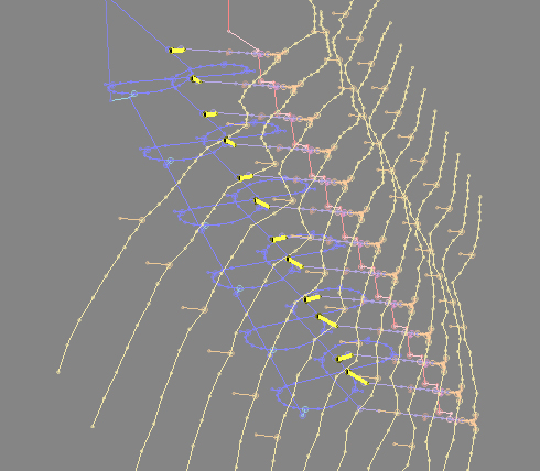
For your first rule, you are going to define dependencies between the above data and the level access data, represented in your project by the following design data: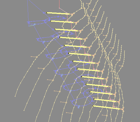
This level access data passes an existing "LVL_ACC" filter (this was also imported in a previous section). - In the table on the right, change the From - Filter to select the [DECL_ACC] filter.
- Group Position is
important; it determines the actual point (within the group of
activities associated with decline access data) from which a search
will be made for the successor activity (in this case, level access
design data).
In this case, [End] is correct. - You won't be using any override settings in this tutorial, so leave Link Position as [None]. More information on Link Position settings can be found in your context-sensitive help,
- The To column group
determines the activity successor, in this case level access activities.
Select [LVL_ACC] from the To - Filter drop-down list. - You want to link the end activity from each decline access to the start activity of each level access. As such [Start] is the correct Group Position.
- Choose which end of the dependency to use as the search Origin. In this case, select [From] (a search will be made from the predecessor decline access activity).
- You want to hook up decline and level access structures providing they are within 15 meters of each other in any direction, so the next step is define your search rules, as described in the following section.
Exercise 3: Define Search Ellipsoid
Spatial-based dependency rules associate one or more activities according to whether data passes a filter, and the proximity of successor data in 3D space (which is also defined by a filter).
In a simple sense, activities A and B could be automatically linked
by a start-end relationship providing they are within 5m of each other
in any direction e.g.: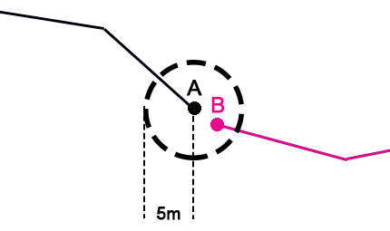
In the following exercise, you will define a spherical search ellipsoid of 15m radius. This will be used to locate level access activities within 20m of the end of each decline access string.
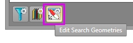
- Before you can select a search geometry (ellipsoid),
you have to define it. Click Edit
Search Geometries:
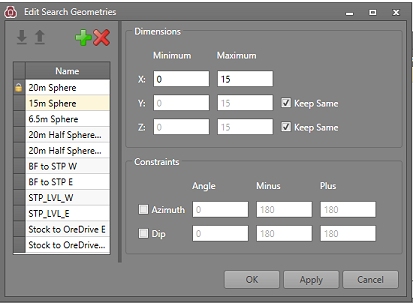
- In the Edit Search Geometries panel, click the "+" button on the left.
- Edit the "New Search Geometry" Name to read "15m Sphere".
- In the Dimensions section on the left, enter a Minimum
value of "0" (zero) and a Maximum
value of "15".
The Minimum value of zero indicates that the entire search sphere is active (i.e. any activity points that pass the successor filter, and fall within the sphere, will be linked to the predecessor activity). Non-zero values let you specify a 'dead zone' within the search geometry, For your project, zero is fine. - The Y and Z fields are both set to Keep Same. This is the simplest way to create a spherical search volume (all ellipsoid axes will be of equal length).
- As a sphere, it isn't necessary to restrict the orientation of the search ellipse during the search. As such, your search geometry for the current rule is complete.
- Before you close the dialog, import the other geometries that
your project will use by selecting Import in the top left of the
panel:

- Locate and open the file "SearchGeometries.xml" in your project folder's XML sub-folder.
- This automatically defines the remaining geometries for your
project. In total, there are 11 geometries that will be referenced
by your dependency rules:
- Click OK to dismiss the Edit Search Geometries panel.
- Back in the Edit Dependency Rules dialog, click inside the Search - Geometry field and select [15m Sphere] from the drop-down list.
- As your search geometry is a sphere, its alignment is irrelevant so you can leave the Azimuth Alignment and Dip Alignment fields set to the [World] axes.
- Finally (for this rule at least), change the Dependency Layer to [Development]. All dependencies created by this rule will be added to the Development layer defined in the previous exercise.
- There are another 6 rules required for the "LEVEL"
rule set. These are created using "+" to add a row to
the table and then populating the rule definition, repeating untill
all 7 rules are defined for level development activities.
Define these additional rules (hover over the Filter name to see the logic behind the rule):From
To
Search
Dependency Layer
Filter Group Position Link Position Filter Group Position Link Position Origin Geometry Azimuth Alignment Dip Alignment  LVL_ACC
Any None SERVICES Start None From 6.5m Sphere World World Development LVL_ACCAny None SUMP Start None From 6.5m Sphere World World Development LVL_ACCAny None VENT_ACC Start None From 6.5m Sphere World World Development VENT_ACCEnd None VENT_RSE Start None From 15m Sphere World World Development DECLINEEnd None LVL_ACC Start None To 15m Sphere World World Development VENT_ACCAny None VENT_ACC Start None To 6.5m Sphere World World Development
|
|
The first two rules in the table are very similar; you could use the Copy function to create the next two rows, then edit the To - Filter to save time. |
Exercise 4: Import the Remaining Rules
The remaining dependency rules are available in an XML file. To save you typing them all in, you can import them just like other UG planning parameters.
-
In the Edit Dependency Rules dialog (Spatial Based Rules tab), click Import:
-
Locate and open the file "Dependencies.xml" in your project folder's XML sub-folder.
-
Three additional rule sets will appear. These represent the remaining dependency rules for your project.
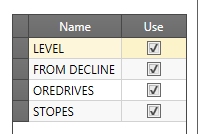
-
Select each of the [FROM_DECLINE], [OREDRIVES] and [STOPES] rule sets to see the rules they contain.
-
Click OK in the Edit Dependency Rules panel to return to the Dependencies panel.
Exercise 5: Generate Dependencies - First Run
In the following exercise, you will automatically generate the dependencies for your project based on the rules defined earlier. The hard work is done (although in the final exercise for this section, you get to break things then correct your deliberate mistake).
-
Enable Show Output.
-
Click Process Rules.
In a similar way to processing (described in the previous tutorial section), a dependencies report is displayed, highlighting errors, warnings and messages. In your case, you should see only messages, with the final entry stating "Processing Completed" (and the current date) e.g.: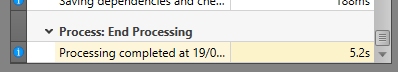
-
To visualize the automatically-generated dependencies, you have to Load Designs:
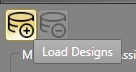
-
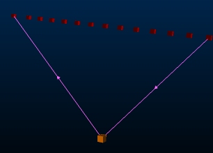
Displaying all of your data will take a few seconds. Once displayed you will be able to see the dependency arrows that have been formed by your rules, e.g.:
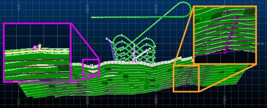
The pink arrow on the left results from one of the LEVEL dependency set rules and has been assigned to the "Development" dependency layer (which is set to pink line formatting). The purple arrow on the left results from one of the STOPES dependency set rules, which is assigned to the "Stopes" dependency layer.
In the next exercise, you'll introduce a manual dependency that also introduces a problem to be fixed.
Exercise 6: Sabotage Your Dependencies Manually
In the following exercise, you will introduce a start-end dependency between one of the level access activities and the decline. In other words, you're going to request that the level access starts before the decline has been developed to reach it. This will contravene your other dependency rules (which are far more sensible) but it's for example only.
-
When specifying manual dependencies, it is useful to set up custom 3D window formatting. This keeps the display area as empty as possible, displaying only areas of interest.
Using the Sheets control bar, switch off the display of all wireframes and strings. -
Also using the Sheets control bar, switch off the display of the DER_Points and WFM_Points points object default overlays.
-
Double-click the FXS_Points points overlay and, using the Points Properties dialog - Symbols tab, set the following properties:
-
Type: 3D
-
Scale: 3
-
Color: select Legend, the [_Z_Coord] column and choose to use the default legend.
-
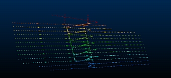
Click OK to update the view of the FXS activity points in the 3D window.
-
Disable the view of the 3D window grid e.g.:
-
Each of the displayed points represents a distinct activity associated with a fixed cross sectional volume.
To introduce a forced error into your project, you're going to define two start-finish dependencies between two different elements of your design. This will create a 'dependency loop' (e.g. activity A relies on activity B being completed, but activity B relies on activity A being completed, and so on). -
Use the View ribbon's Zoom East command to zoom in and display a clear view of the data:
-
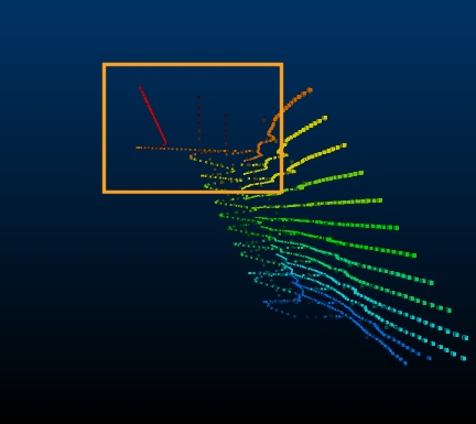
Zoom Area and select the area below:
-
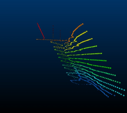
You should be looking at something like this:
-
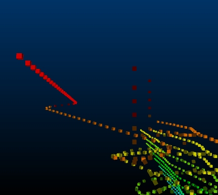
Use the Quick Filters control bar to display only data where DESIGNDF = DECLINE or DESIGNDF = LVL_ACC, i.e.:
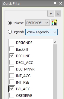
Your display should now look like this: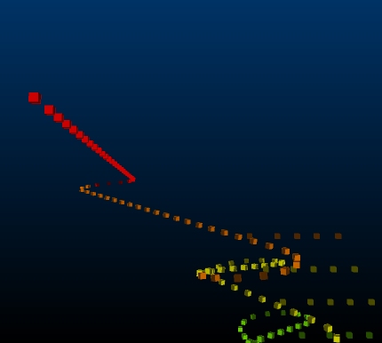
-
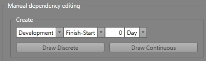
In the Dependencies panel, in the Manual dependency editing section, use the drop down lists to select the [Development] layer and a Finish-Start constraint with zero lag, i.e.:
-
Select Draw Discrete (this option is used for simple point-point dependency setting - the Draw Continuous option is used to daisy-chain multiple activity dependencies).
-
Click two points as shown in the image below (the order is important):
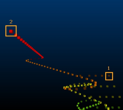
The first point is at the start of the decline and the second is on one of the ventilation shafts. -
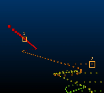
Define a second dependency by clicking the following 2 points (you are already in dependency editing mode so simply have to click two more points):
-
Using the Sheets control bar, enable the Development strings overlay. You can now see the prob;ematic dependency you just created:
-
Click Draw Discrete again to disable interactive dependency editing mode.
-
Click Save to update your database with the new dependency information.
-
Now, click the Dependency Loop Detector at the bottom of the panel:

-
The table below displays a problem:
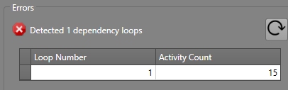
This shows that a cyclic dependency has been found, which currently impacts 15 activities (the total number of activities in the decline string between the manual dependency predecessor and successor nodes, plus the activity on the decline access string to which they are linked). -
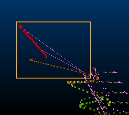
Click the Loop Number cell of the table. This automatically filters out all non-relevant data and zooms the dependency loop into view:
-
Time to put things right: click the Delete button in the Manual dependency editing section, then select both dependency strings to delete them.
-
Re-run the Dependency Loop Detector. This time no dependency loops are reported.
-
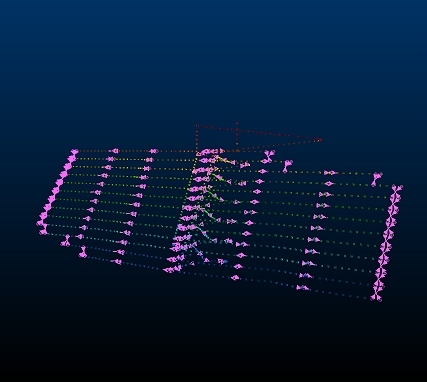
Zoom out to see all of your automatically-generated dependencies and activity points:
-
Click Save to update your database, then close the Dependencies panel.
-
Unload your 3D window data (type 'ua' with your cursor in the 3D window. Click Yes at the prompt.
-
Save your project.
You're now ready to export your schedule information to EPS and view an animation of the schedule playback. This is described in the next section.
