Print Viewport Objects
You can print any view in the Viewport, including hole patterns and 3D reports.
Tip: If you want to highlight some holes in a printed report, consider changing the Collar Appearance or Collar Flag Colour properties in the Properties Pane for those holes. For example, you might create a CAD print border with a key of different collar shapes for holes with different angles. You could filter holes by angle range, select the holes and change their collar appearance before printing.
This video, recorded using an earlier version of DataBlast Pro, provides an example of how to print a map.
Activity Steps
- Display the required objects in the Viewport.
Note: If you are printing multiple patterns, the Dim Inactive Patterns for CAD Printing setting in the in the Local Settings screen controls the brightness of inactive patterns.
- On the applicable ribbon menu, click Print. See Menus.
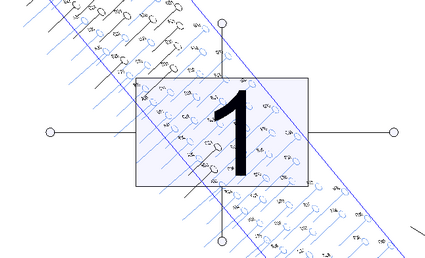
A print area selector displays in the Viewport and the Print Settings screen displays.
The rectangle of the print area selector indicates which objects will be printed within the print borders. See Maintain CAD Print Borders.

Tip: You can still access the Layer Control screen from the Layers toolbar if you want to change which layers are visible or hidden.
- Select the Print Type from:
- Printer
- PDF File—Prints data in layers, which can be hidden or displayed when the PDF file is viewed in an application such as Adobe Acrobat Reader.
- If Print Type is Printer, select the Printer.
- Select the Paper Size.
- Select the Orientation from Landscape and Portrait.
- To adjust the size of the print area selector, edit the Print Scale.
- To move or rotate a print area selector:
- Click the print area selector.
- Drag the print area selector by a rectangle corner or centre to move it, or by one of the extending lines to rotate it.
- To print the Viewport objects across multiple pages, click Add Page as required.
New print area selectors have the same orientation as the previous print area selector.
- Select whether to print in Black and White.
- Select whether to print in 2D Wire Mode. If checked, when you print to PDF, the data is in layers that you can hide or display. For example, if you print a drill pattern, the layers include the borders, holes, hole IDs and hole pattern boundaries. If unchecked, only the borders can be hidden in the PDF.
- To override the default text strings in the print border:
- Click Edit Border Text Items.
The Text Border Items Override screen displays.
- For each Item Key, enter the Display String as required.
- Click Apply.
- Click Edit Border Text Items.
- To preview each printed page, click the PAGE 1 tab (and so on) below the Viewport.
- Click Print.


