
Road Network Settings
To access this screen:
-
Project Settings >> Road Network.
This form allows you to maintain the road network needed by the Haulage Analysis or the Optimization option in DTS Blend.
A Road Network defines road segments between Nodes for haulage calculations. Use this screen to enter the segments and their travel conditions for Haulage Analysis and the Optimisation option in Blend.
A Node is a named connection point in the road network. A road segment is the link between Node 1 and Node 2.
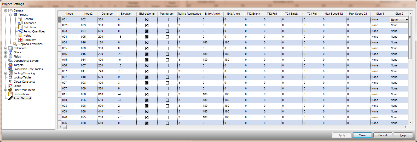
An example of road network settings for a project
Activity steps:
-
Display the Road Network screen.
-
To add a road segment:
-
In the grid, add a new row.
-
In Node 1, enter the start Node name.
-
In Node 2, enter the end Node name.
-
In Distance, enter the road distance between the nodes.
Note: If the segment represents a curved road, enter the distance along the road, not the straight-line distance.
-
In Elevation, enter the elevation change between the nodes.
Note: Use the same unit system as Distance.
-
If trucks can travel in both directions on this segment, select Bidirectional.
-
If a pantograph is available on this segment, select Pantograph.
-
In Rolling Resistance, enter the rolling resistance coefficient for the segment.
Tip: Use the project standard value if you do not have a site value. The default is typically 3%.
-
In Entry Angle [degrees], enter the segment entry angle at Node 1.
-
In Exit Angle [degrees], enter the segment exit angle at Node 2.
-
If you want to set fixed travel times, enter values in the applicable travel time fields:
-
T12 Empty and T12 Full for travel from Node 1 to Node 2.
-
T21 Empty and T21 Full for travel from Node 2 to Node 1.
Note: Enter 0 to let the system estimate travel time.
-
-
If you need to limit speed on the segment, enter:
-
Max Speed 12 for travel from Node 1 to Node 2.
-
Max Speed 21 for travel from Node 2 to Node 1.
-
-
If the segment has signs at the exits, set:
-
Sign at Exit 1 for the sign when leaving the segment at Node 1.
-
Sign at Exit 2 for the sign when leaving the segment at Node 2.
-
-
-
You can create groups of table rows by adding unique values into the Group field.
-
Click OK to update your project.
-
Save your project.
Related topics and activities: