
Convert to Surface Mesh
The Convert to Surface Mesh application generates a surface mesh from 2D data (points or grid) with an elevation variable or from 3D points.
-
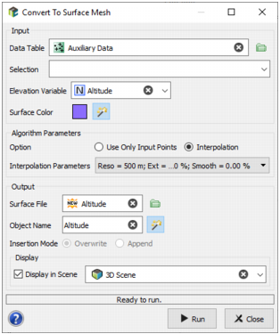
Input:
- Data Table: Click the directory icon to open a Data Selector and select the Data Table on which you want to apply the Convert to Surface Mesh task. The Data Table can also be dragged and dropped directly from the Data tab. The data can be of any dimension, 2D or 3D. In case of 2D data, an elevation variable will be asked. They can be points or grids in 2D, and only points in 3D. If you select another kind of data (borehole assays for examples), they will be considered as points.
- Selection: You can define an optional Selection variable to consider only a subset of the data table.
-
Elevation Variable: The Elevation Variable is required only if the input data table is 2D. Select here the variable which will be considered as the elevation to generate the surface.
If the input data table is a 2D grid, several surfaces can be generated at a time. In this case, click the
 /
/  buttons to add / delete elevation variables.
 - Surface Color: Click the colored square to open the Color Selector and select the Color which will be automatically used to display your mesh. This color will be saved in the Sub Domain variable. It can be modified later by editing the catalog associated to this variable (by editing the variable properties).
-
Algorithm Parameters:
-
Option:
- Use Only Input Points: The surface is generated using a Delaunay mesh generator, which only triangulates the input points.
-
Interpolation: If the input points are 3D, they are projected on their median plane obtained from PCA (for 2D points, the median plane is assumed horizontal), then the projected points convex hull is computed and meshed using CGAL and the provided resolution, and finally the projected z - or elevation - variable is smoothed using kriging at the mesh vertices points. This method requires the following Interpolation Parameters:
- Mesh Resolution: Maximum distance between vertices (default value = 1% of the input data bounding box);
- Mesh Extension: Optional extension to add around the data convex hull (default value = 0);
- Smoothing Ratio: As the surface is smoothed from kriging, the nugget effect can be set. Hence, the higher the smoothing effect, the planer the surface. On the contrary, if it is low, the surface will be more interpolating the input points (default value = 0%).:
Note: Surfaces generated from 2D grid data can show some holes due to undefined values or to a selection. On the contrary, surfaces generated from Points data are always connected.
-
-
Output:
- Surface File: Define here the new output Mesh file to be created.
- Object Pattern: By default the names of the generated surface(s) in the output mesh file will be the same as the input variable(s) (using the %file pattern if a single elevation variable is provided, %var in case of several surfaces). You can modify this pattern to add a prefix or a suffix to the surface name.
-
Insertion Mode: This mode is only available if the provided surface file already exists.
- Overwrite: The output mesh file is completely overwritten, hence all the existing surfaces are deleted and replaced by the generated one;
- Append: The generated surfaces are appended to the output mesh file. Hence, the output mesh file simply contains the union of pre-existing surfaces with the generated one, only overwriting the intersection (matching pre-existing surfaces are replaced by generated one).
- The output surface mesh can be displayed in a 3D view in the standard way (Drag & Drop from the Data Explorer to the 3D Viewer) at the end of the run. However it is possible to automatically display the result of the run by ticking the Display toggle and selecting a 3D scene. A layer will be created in the corresponding 3D scene.
- Click Run to launch the task and create the mesh file.