
Create convex hull
This tool is designed to automatically create a convex hull (a polygon or a mesh) which surrounds the data. The convex hull takes a scatter plot on input and generates a convex envelope surrounding its vertices. This may be visualized as the shape enclosed by a rubber band stretched around the data. An extension can also be considered.
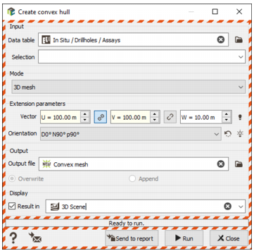
- Input: Click the directory icon next to Data table to open a Data Selector and select the input data where you want to consider to create a convex hull. Data can be of any type but it will be considered as a points file. For example, if you select an assay data table, we will read the gravity centers (and not the from/to coordinates). The data table can also be dragged and dropped directly from the Data tab. You can associate a Selection variable to filter samples on which the convex hull will be calculated.
-
Mode: Three modes creating a different kind of file are available. Depending of the mode, Extension parameters are provided.
- 2D polygon: a 2D polygon file is created. If the input data table is 3D, we only consider the X/Y coordinates (not Z). Define an Extension if you want to consider a buffer around your data to build the final polygon. This distance is set to 0 by default (i.e. no extension).
-
3D polygons: This mode is only available if the input data table is 3D. A set of 3D polygons defined by slices is created. Polygons are defined by setting a Reference elevation to start the vertical slicing (which can be outside the data/polygons definition) and a Slice height which corresponds to the vertical polygon width. Each polygon can also be extended horizontally setting an Extension. This distance is set to 0 by default (i.e. no extension).
Note: A 3D polygon is a 2D polygon with a thickness defined by a minimum and a maximum value for Z. A 2D polygon cannot contain any 3D polygon and vice versa.
Note: The algorithm requires at least 3 points to generate a valid polygon. The selected points cannot be perfectly aligned. If these requirements are not satisfied, an error message will be popped up.
- 3D mesh: This mode is only available if the input data table is 3D. A 3D mesh file describing a volume around the data is created. The computed mesh can be extended by setting distances along U/V/W. By default, distances are equal to 0 (i.e. no extension) and the extension is isotropic (i.e. the values along U, V and W are the same). If you set different values, an Orientation is required too.
-
Output file: Click the directory icon to open a Data Selector and define the name and location in your Isatis.neo project of the new Polygon / Mesh File you want to create. If the file already exists, you have two options:
- Overwrite: the output file will be erased and created again. It will only contains the created polygon/mesh.
- Append: the created polygon/mesh will be appended to the existing file as an additional object.
- Tick the Display toggle and select a scene (2D or 3D) to automatically add the layer/item associated to your polygon/mesh file at the end of the run in the Map or 3D Viewer.
- Click Run to create the polygon/mesh. The new file will be directly visible in the Data tab.