
Create Grid
Objective
This tool allows you to create a grid file in two or three dimensions.
The Creation mode is either ‘Free’, ‘From auxiliary data’, or ‘From an existing grid’. These three cases are detailed in the sections below.
Throughout this page, references are made to X, Y, and Z (in 3D), but if the grid is rotated, then these should be considered as the rotated axes of the grid.
Interface
Dimension
The Dimension is either 2D or 3D.
Creation Mode
-
Free
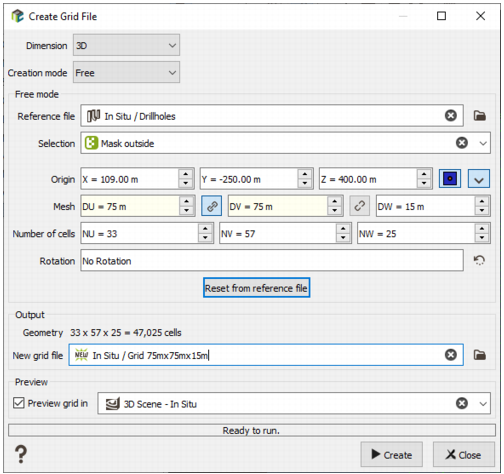
In this mode, grid parameters can be set freely by the user.
-
Reference file (optional): If a file here is chosen with the Data Selector or by drag and drop directly from the Data table, then clicking the button ‘Reset from reference file’ will populate the grid parameters so that the grid covers the bounds of the data contained in the Reference file.
Note: Clicking this button will overwrite any previously set parameters. To fix the grid cell size and fit to an auxiliary file, use the ‘From auxiliary data’ mode.
- Selection (optional): A selection applied to the Reference File.
-
Origin: The X, Y, and Z (if 3D) coordinates of the origin. If the grid has no rotation applied, then the origin is always at the lower-left of the grid in X and Y, but there is an option to choose if the Z value is at the top of the grid or the bottom of the grid.
-
 indicates that the coordinates are of the center of the grid cell.
 -
 indicates that the coordinates are of the corner of the grid cell.
 -
 (in 3D) indicates that the Z-coordinate of the origin is at the lowest level of the grid.
 -
 (in 3D) indicates that the Z-coordinate of the origin is at the highest level of the grid.
-
- Mesh: The dimensions of the grid cells in X, Y, and Z (in 3D).
- Number of cells: The number of grid cells in each direction (X, Y, Z).
- Rotation: A rotation to apply to the whole grid.
-
-
From auxiliary data
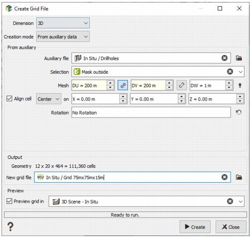
In this mode, the created grid will have the grid cell size set by the user, and will cover the spatial extent of the auxiliary file.
- Auxiliary file: The auxiliary file, which the created grid will cover. The file may be of points or borehole data, or could be a polygon or mesh file (wireframe).
- Selection (optional): A selection on the auxiliary data table.
- Mesh: The dimensions of the grid cells in X, Y, and Z (in 3D).
-
Align cell: If activated, then the origin will be set so that either a Corner or Center (as chosen by the user) would be at this location. Note that this alignment point may be outside the bounds of the grid.
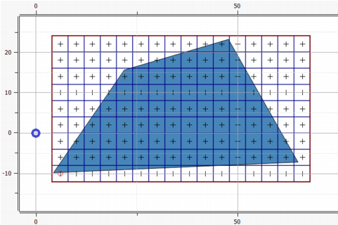
In the example below, the grid is fitted so that it covers the polygon drawn in blue, with a corner aligned to (0, 0). This alignment point is shown below as a blue circle, and is outside the grid. But if the grid were to be extended to the left, then a corner of the cell would be at the alignment point.
- Rotation: A rotation to apply to the grid.
-
From an existing grid
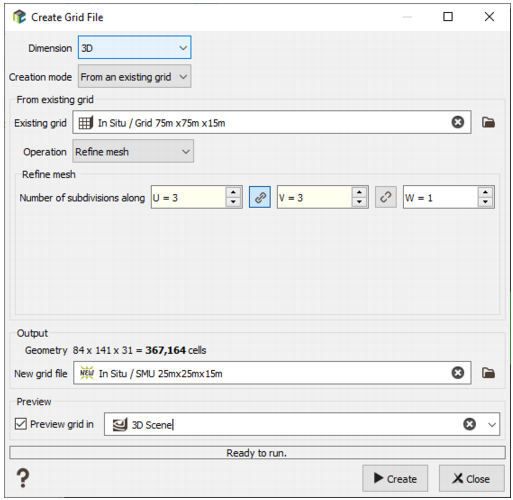
In this mode, the grid geometry will be made to match that of an Existing grid, with some Operation performed on the existing grid’s geometry to create the new grid.
The possible operations and their parameters are detailed below.
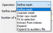
- Refine mesh: Each cell of the existing grid is subdivided into an integer Number of subdivisions along U, V, and W (in 3D) to create the new grid. For example, if a 2D existing grid has a cell size of 12m × 12m, and the number of subdivisions is 6 in U and 4 in V, then the new grid will have cell sizes of 2m × 3m.
- Coarsen mesh: Each cell of the new grid will cover an integer number of cells of the existing grid. The Number of cells to be merged along U, V, and W (in 3D) defines how many cells of the existing grid in each direction the new grid cells will cover. For example, if a 2D existing grid has a cell size of 12m × 12m, and the number of cells to be merged is 3 in U and 4 in V, then the new grid will have a cell size of 36m × 48m.
- Enter new mesh: The (corner) origin of the new grid will be the same as the (corner) origin of the existing grid, and the user enters a New mesh (cell size). The new grid will cover the existing grid.
- Fit to selection: The geometry of the new grid will match that of the existing grid, but the grid extent will only cover those cells inside a chosen Selection on the existing grid.
- Extract from indices: A subset of the existing grid is extracted according to the Minimum cell and Maximum cell in X, Y, and Z (in 3D). These indices are the values of the IX, IY, and IZ (in 3D) variables in the existing grid file. The minimum index value is 1.
- Expand: The new grid is larger than the existing grid, with an integer number of extra cells added in U, V, and W (in 3D) to the Lower and Upper sides of the grid.
- Expand to auxiliary file: Extra cells are added in each dimension so that the new grid covers an Auxiliary file, optionally limited to a Selection on the auxiliary file.
Output
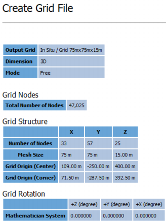
- Geometry: This field is just an echo of the number of cells along X, Y, and Z (in 3D), as well as the total number of cells of the created grid. This information can be useful to realize the create grid file contains a huge number of cells (which will take some place on disk and could generate important computation times).
- New grid file: The name of the grid to create.
- Click Run to create the new grid. If the file already exists, a warning message is printed to ask you for confirmation. After confirmation, the previous file will be deleted and rebuilt.
The parameters of the newly created grid are printed to the Messages window.
The output grid can be displayed in a 2D/3D view using the drag & drop from the Data Explorer to the Map/3D view at the end of the run.
Preview
When creating the grid, ticking this option allows to visualize the final grid in the Map or in the 3D Scene, depending on the user’s choice. If the parameters (cells number, mesh dimension, etc.) change, the previewed grid will adapt on live.