
Create Sub-block Model from Meshes
Objectives
In Isatis.neo, block models are generally defined as regular grids, each cell corresponding either to a panel to be estimated or a SMU (Selective Mining Unit). To better fit the geometry of the deposit, a Sub-Block Model can be defined. This Sub-Block Model is useful to display the estimation or simulation results. The common practice is to first estimate or simulate the regular block model (parent cells) and then copy the variables from the regular model to the sub-block model. The sub-block model can also be estimated directly (see kriging module documentation).
The Sub-Block Model from Meshes application is meant to build such a Sub-Block Model from an existing regular grid (for example the block model containing the panels estimation) and a set of 3D surfaces.
The Sub-Block Model is stored as a point file having a Compound Variable of type "Block Definition". This compound variable stores the size of each sub-cell of the model.
Pre-requisites
You need an existing 3D block model (a regular grid) to define the geometry of the parent cells and a set of 3D mesh files. The mesh files can be used to define the boundaries and/or make the sub-division into multiple domains.
Building the Sub-block Model
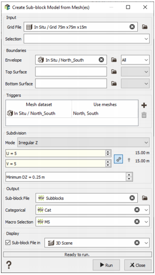
Defining the geometry of the parent cells
An existing regular Grid File must be selected. The geometry of this file will define the size of the parent cells. Each parent cell will be refined if at least 50% of the sub-block volume is inside the boundaries of the envelope or if it crosses one of the optional trigger surfaces. Each cell which is completely outside the boundaries will be omitted from the sub-block model.
A Selection variable can be applied to filter the nodes of the input grid. Sub-blocks will be created only for the selected cells (not for the entire grid).
Note: If the selected input grid file is a sparse grid, we will create sub-blocks only for the cells of the sparse grid (i.e. only for the active cells of the sparse, not on the entire grid).
Defining the boundaries
The Boundaries can be defined with up to 3 optional mesh files:
- The Envelope mesh file which is a closed mesh (solid). No sub-block will be created outside of this envelope. If there is no envelope file, the borders of the regular grid will be used as a limit. Overlapping meshes are not supported.
-
The Top Surface file which is an opened triangulated mesh. No sub-block will be created above this surface.
Note: If the surface does not cover the whole extension of the Grid file, sub-blocks will be created where a vertical line crosses the surface.
Note: When the grid is tilted, the top surface should be considered as relative to the grid (the "vertical" direction is aligned with the W direction).
- The Bottom Surface, has a similar role as the Top Surface: no sub-block will be created below this surface.
Defining the trigger surfaces
By default, each parent cell which is completely inside the boundaries is not refined. When one or more trigger surfaces are defined, each parent cell crossing one of these surfaces will be refined to better follow some geological contacts.
The trigger surfaces can be opened or closed meshes. When using closed meshes as triggers, the application can create an optional categorical variable which can be used as a domain identifier. Note that if one closed mesh intersects another, the domain id will correspond to the first encountered solid.
Defining the Subdivisions
Each parent cell crossing one of the boundary meshes or one of the trigger meshes will be refined. For each main direction (U, V and W) of the grid, you have to define the maximum number of Subdivisions.
Along the U and V directions, the refined sub-cells will have the size of the parent cell divided by the number subdivisions.
Along the W direction, two modes are available:
- The Regular Z Mode requires a number of subdivisions for Z. The sub-cells will have a size which is a multiple of the smallest size. The smallest size is the size of the parent cell divided but the number of subdivisions along W direction.
- The Irregular Z Mode mode asks for a minimum size for Z. It enables a better fit of the generated sub-block model to the input envelope and/or surface(s).
Output
The name of an output point file must be provided. This file will contain the centroids of the sub-cells (X, Y, Z) and the size of sub-blocks (Compound variable named "Sub-block Definition"). The Sub-block definition contains also the global rotation of the grid.
The file will also contain a "Sub-block IJK" variable which can be used later to copy variables from the regular grid file to the sub-block file. This is an integer variable.
Optionally, when Trigger meshes are defined, a Categorical variable and a Macro Selection variable can also be provided.
The Categorical variable is generated from the sub-domain ids encountered in the trigger files. The colors coming from the input mesh are kept.
The Macro Selection variable will contain as many alphanumeric indices as the number of encountered sub-domain from the trigger meshes. Each selection indicates whether the sub-cell is inside the corresponding solid or not.
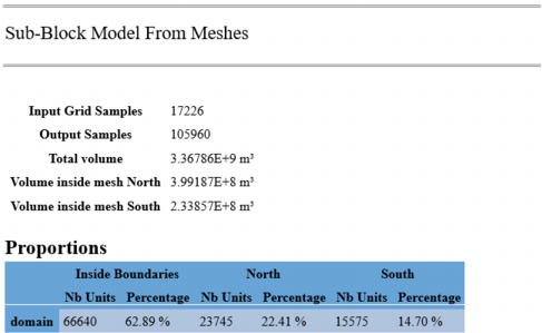
Example of end of run output (message window):
Filling the Sub-block Model
The most common way to fill the sub-block model is to copy variables (for example kriging results) from the regular grid. The most efficient way is to use the Copy Using ID tool. This tool can be accessed from the ribbon: Data Management / Data Transfer / Copy Using ID.
An alternative is to perform the estimation directly in the Sub-Block file. The kriging module has an option to define the discretization by giving the spacing between discretization points.
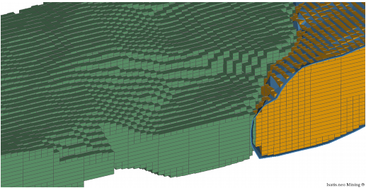
Displaying the Sub-block Model
The variables from the sub-block model can be displayed in a 3D view using the standard way (Drag & Drop from the Data Explorer to the 3D view). The display detects the presence of the "Block Definition" compound variable containing the sub-block sizes and automatically adapts the rendering of the data. The centroids of the sub-blocks can be displayed as points by starting the Drag & Drop operation using the right button of the mouse.