Mesh File Import
The Mesh File Import enables you to import files defined as *.dxf, *.dwg, *.obj, *.stl, *.msh, etc. formats. Many software export meshes as *.dxf, *.dwg, *.obj and *.stl formats. Thus, you should not have any issue to get these types of files.
The meshes from Leapfrog software defined as *.msh or *.lfm can also be imported, from both the CAD Mesh file Import or the dedicated Leapfrog Import tasks.
Note: Vocabulary often used among software industry: meshes are also known as wireframes, triangulations or solids files.
Input
-
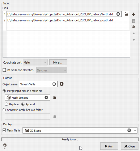
Files: The files in this table will be imported.
Click on the Plus button to add a line in the table. Select the input file(s), click the folder icon to pop up a window file selector. You can select files with different extensions.
Click on the Bin to delete the selected line.
Click on the cross to clear the full table.
- Coordinate unit: Select the length unit of the coordinates XY(Z). The unit must be the same for all the coordinates. If your unit is not available, click on "More..." to define a new unit.
-
2D mesh and elevation: activate this option when the mesh file is defined in 2D, with XY coordinates and a chosen elevation variable. It is flat.
When this option is not activated, a 3D mesh will be imported with XYZ coordinates, an area and a volume.
- Elevation output variable: write the name of the elevation variable in the output file.
- Elevation input unit class: Select the unit class of the elevation variable. By default, it is Elevation. This field is available only in case of "2D mesh and elevation".
- Elevation input unit: Select the elevation unit of the chosen elevation variable. This field is available only in case of "2D mesh and elevation".
Output
- Object name: enter the name of the objects in the mesh file. A pattern should be entered so that the objects will be easily identified. The default is set to %mesh.
-
Import mode
-
Merge input files in a mesh file: the files from the list are all imported as objects in a single mesh file. Enter the name of the mesh file. Two writing modes are available:
- Replace: if you want to create a new file in which you will store your data. In case where the output file already exists, this one will be overwritten.
- Append: if you want to append your data to an existing file. This way, the mesh file will contains several objects.
- Separate mesh files in a folder: one folder is created in the Data explorer and contains the individual meshes. Enter the name of the folder.
-
- Color: the color defined in the input file is used when present, in the other case the color is randomly chosen.
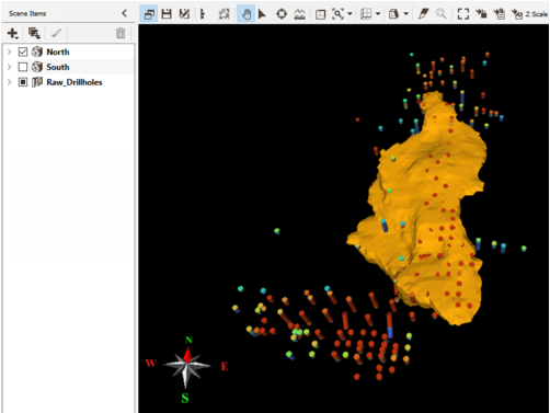
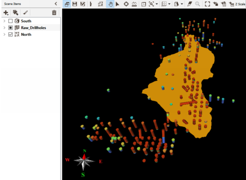
- Tick the Display toggle to display the imported data in a defined scene (2D or 3D) at the end of the run. The display item will be the Mesh surface facets with the color variable.
- Click Run to end the import task.
- Press Close to abort the import task.
After the import, the new mesh file appears in the Data explorer. When extending the content, there are several data tables inside: Meshes which defines the object(s) of the file; Mesh vertices which defines the vertices (the lines); Mesh surface facets which defines the facets; Mesh cells which defines the cells (only in 3D).
Note: The Mesh Cells data table is only available when the mesh is 3D.


