
Distortion Option
This option allows to deform the reproduced pattern. The weakness of MPS methodology lies in the training image requirement. In 3D, it can be hard to obtain this image. With distortion capabilities, we can start from simple theoretical images, distort and combine them to build more complex images. This option is also very useful to "extrapolate" mineral properties from a characterized mine to a similar (but different one) for instance. This deformation can be global or local, and can be a Scaling and/or Rotation property.
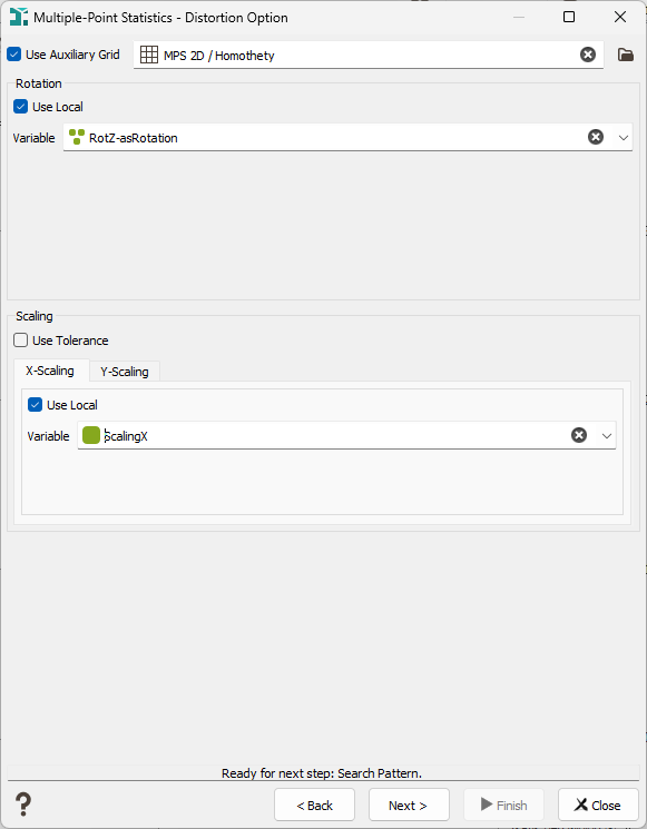
- Use Auxiliary Grid: A local distortion, either a rotation or a scaling, can be defined on an auxiliary grid. In this case, the variables will be migrated in the simulation grid using a bilinear interpolation method.
-
Rotation: The structures defined in the training image need to be stationary, but can have an anisotropy, or a preferential orientation. A rotation can be used to simulate structures in another direction in the simulation grid. The angle(s) represent the needed rotation in the clockwise direction from the training image to the simulated orientation.
It is either possible to give a :
- Global Rotation without Tolerance: In this case, you have to define the homogeneous rotation value to be applied to each node of the simulation grid. The rotation is defined by a unique angle in 2D, or three angles in 3D.
- Local Rotation without Tolerance: In this case, you have to define the rotation variable to be applied for each node of the simulation grid. The rotation variable must be a compound rotation variable. In that case, the Use Local checkbox must be checked to select the local variable name.
-
Scaling: The scaling can be defined for each dimension X, Y (and Z). We can also mix the type of scaling. For example, it could be local without tolerance on X, global with minimum and maximum tolerance on Y and global with reference and deviation tolerance on Z. Depending on the parameters, we have several scenarios:
- Global Scaling without Tolerance: In this case, you have to define the scaling value to be applied to each node of the simulation grid. The scaling value must be greater than 0.
- Global Scaling with Minimum and Maximum Tolerance: In this case, you have to define the minimum and maximum scaling values to be applied to each node of the simulation grid. The minimum and maximum must be different and greater than 0.
- Global Scaling with Reference and Deviation Tolerance: In this case, you have to define the reference and deviation scaling values to be applied to each node of the simulation grid. Reference and deviation must be different than 0. and reference/deviation must be greater than 0.
- Local Scaling without Tolerance: In this case, you have to define the scaling variable to be applied for each node of the simulation grid. The scaling variable must be numerical and the values must be a greater than 0.
- Local Rotation with Minimum and Maximum Tolerance: In this case, you have to define the minimum and maximum scaling variables to be applied for each node of the simulation grid. The minimum and maximum variables must be different. Also, the scaling variables must be numerical variables and for each node, maximum must be greater than minimum and both values must be different from 0.
- Local Rotation with Reference and Deviation Tolerance: In this case, you have to define the reference and deviation scaling variables to be applied to each node of the simulation grid. The reference and deviation must be different. Also, the scaling variables must be numerical variables and for each node, reference and deviation must be different from 0. Reference/deviation must be greater than 0.