
Boolean operations
The boolean operations are mathematical (geometrical in the case of meshes) operations on closed objects. They analyze the location of objects in the space and their interaction.
Boolean operations are especially useful when the objects are overlapping between each other. It allows to detect the common zone, to take one apart from the other, to create a bigger one from the little pieces.
 between two objects.")
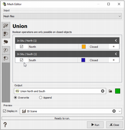
Union
This mode allows you to perform the Union boolean operation from several closed mesh files to get a new mesh file containing the parts of all selected meshes. A rearrangement of triangles is operated if necessary. This operation can be recorded in a batch file.
Note: Only the closed mesh files can be used for the boolean operations.
-
In the central area there are different sections, one per input mesh file. On the dark grey line, there is the name of the mesh file, followed by a number which corresponds to the number of selected objects in this mesh file. For each input mesh file, a table lists all the different objects contained inside. The section can be shrinked with the little arrow on the top right.
The columns headers are:
- Selected: shows if the object is selected or not to be combined. One or several objects can be selected by ticking the check boxes. Only the selected objects will be combined. The vertices of the selected objects are displayed in the scene with a green color.
- Object name: shows the object name (it corresponds to the Name variable referenced in the Meshes data table). This is a read-only information.
- Color: displays the object color (the same as the one referenced in the catalog of the Color variable of the Meshes data table). This is a read-only information.
- Mesh type: details the nature of the object. The categories are undetermined/open/closed. This is a read-only information.
-
Display: displays the object in the 3D scene by opening or closing the eye icon. To display the objects, the section "Display" and a 3D scene must be activated at the bottom of the interface.
The task computes the table as soon as the input file(s) is (are) provided.
- Output: Enter the name of the output mesh file which is the result of the boolean operation or click the directory icon to open a Data Selector. If it already exists the mesh can also be dragged and dropped directly from the Data tab. Select the color of the mesh.
-
Modes
- Overwrite: it creates the combined object inside a new mesh file. If the output file already exists, it will be erased and created again.
- Append: if the output file already exists, the selected object(s) will be added to the existing objects.
-
Click Run to perform the operation and create/append the object(s). A report is sent in the Messages window at the end of the run.
Note: The Run is available as soon as two objects are selected.
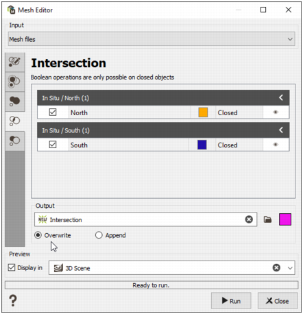
Intersection
This mode allows you to perform the Intersection boolean operation from several closed mesh files to get a new mesh file containing the common part between all selected meshes. A rearrangement of triangles is operated if necessary. This operation can be recorded in a batch file.
Note: Only the closed mesh files can be used for the boolean operations.
-
In the central area there are different sections, one per input mesh file. On the dark grey line, there is the name of the mesh file, followed by a number which corresponds to the number of selected objects in this mesh file. For each input mesh file, a table lists all the different objects contained inside. The section can be shrinked with the little arrow on the top right.
The columns headers are:
- Selected: shows if the object is selected or not to be combined. One or several objects can be selected by ticking the check boxes. Only the selected objects will be combined. The vertices of the selected objects are displayed in the scene with a green color.
- Object name: shows the object name (it corresponds to the Name variable referenced in the Meshes data table). This is a read-only information.
- Color: displays the object color (the same as the one referenced in the catalog of the Color variable of the Meshes data table). This is a read-only information.
- Mesh type: details the nature of the object. The categories are undetermined/open/closed. This is a read-only information.
-
Display: displays the object in the 3D scene by opening or closing the eye icon. To display the objects, the section "Display" and a 3D scene must be activated at the bottom of the interface.
The task computes the table as soon as the input file(s) is (are) provided.
- Output: Enter the name of the output mesh file which is the result of the boolean operation or click the directory icon to open a Data Selector. If it already exists the mesh can also be dragged and dropped directly from the Data tab. Select the color of the mesh.
- Modes
- Overwrite: it creates the combined object inside a new mesh file. If the output file already exists, it will be erased and created again.
- Append: if the output file already exists, the selected object(s) will be added to the existing objects.
-
Click Run to perform the operation and create/append the object(s). A report is sent in the Messages window at the end of the run.
Note: The Run is available as soon as two objects are selected.
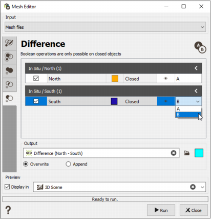
Difference
This mode allows you to perform the Difference (subtraction) boolean operation from several closed mesh files to get a new mesh file containing the difference part only (i.e. the gap). A rearrangement of triangles is operated if necessary. This operation can be recorded in a batch file.
Note: Only the closed mesh files can be used for the boolean operations.
-
In the central area there are different sections, one per input mesh file. On the dark grey line, there is the name of the mesh file, followed by a number which corresponds to the number of selected objects in this mesh file. For each input mesh file, a table lists all the different objects contained inside. The section can be shrinked with the little arrow on the top right.
The columns headers are:
- Selected: shows if the object is selected or not to be combined. One or several objects can be selected by ticking the check boxes. Only the selected objects will be combined. The vertices of the selected objects are displayed in the scene with a green color.
- Object name: shows the object name (it corresponds to the Name variable referenced in the Meshes data table). This is a read-only information.
- Color: displays the object color (the same as the one referenced in the catalog of the Color variable of the Meshes data table). This is a read-only information.
- Mesh type: details the nature of the object. The categories are undetermined/open/closed. This is a read-only information.
- Display: displays the object in the 3D scene by opening or closing the eye icon. To display the objects, the section "Display" and a 3D scene must be activated at the bottom of the interface.
-
Difference identifier: because of the asymmetry of the operation, each used object must be identified as the principal or the subtracted with the identifier selector. The objects is identified with the letter A or B, given that the perform operation is A-B. The remaining set is the difference. The result might be null (empty) if you are not careful in the order.
Note: All the objects identified with the same letter will be merge together before the operation.
The task computes the table as soon as the input file(s) is (are) provided.
- Output: Enter the name of the output mesh file which is the result of the boolean operation or click the directory icon to open a Data Selector. If it already exists the mesh can also be dragged and dropped directly from the Data tab. Select the color of the mesh.
-
Modes
- Overwrite: it creates the combined object inside a new mesh file. If the output file already exists, it will be erased and created again.
- Append: if the output file already exists, the selected object(s) will be added to the existing objects.
-
Click Run to perform the operation and create/append the object(s). A report is sent in the Messages window at the end of the run.
Note: The Run is available as soon as two objects are selected.