
MSO Geometry Parameters
Note: Your MSO Manual contains more detailed information about stope shape framework principles.
Key Stope Geometry Principles
This image highlights key shape principles considered when describing stope shapes generated by MSO:
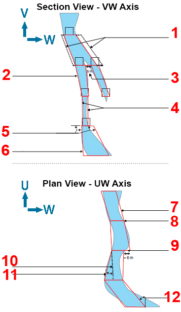
| 1 | Wall (skin) dilution is added to the stope-shape as an equivalent linear-overbreak. The dilutions are added after the optimised stope-shape is formed. |
| 2 | Stope-shapes are simple 4-point trapezoids using straight lines between the levels. |
| 3 | Minimum waste pillar width, for example, 5m. This can alternately create 2 “parallel” stope shapes separated by a waste pillar, 1 larger stope shape carrying the waste between the lenses, or 1 stope shape around the higher contained-metal lens. |
| 4 | Minimum mining width, for example 3m. Note that width represents horizontal trace (not the true mining width). |
| 5 | Wall dip angles: defines the min/max angles for each independent wall . The near/far, hw/fw, min/max range is defined as 0 degrees LHS horizontal, 90 degrees vertical down and 180 degrees RHS (this example is 90-120 degrees) . |
| 6 | MSO stope shape. |
| 7 | MSO stope shape. |
| 8 | Smoothing: stope shape end-walls are “smoothed” when the gap is less than defined target as in this example of <6m. |
| 9 | Smoothing: stope-shape end-walls not smoothed when the gap is greater than defined target (this example >6m). |
| 10 |
Strike angle change: the maximum relative angle between the stope-shape top/bottom wall edges (this example is 30 degrees). It typically represents wall (hw/fw, near/far) “twist”. This is the top edge of the footwall face. |
| 11 | As above, but this is the bottom edge of the footwall face. |
| 12 | Maximum strike angle: the min/max angle (+/- range) relative to the stope-framework U-axis (i.e. the strike direction). This example +/-45 degrees. |
Minimum Stope Width
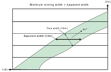
The minimum mining width parameter is defined as distance in the
horizontal plane on the framework section along the W-axis (and consequently
measures the apparent width). If the orebody dip is moderate or the
strike deviates from the framework axis, then it would be appropriate
to make a correction to the width specified to better approximate
the intended true width. As an example, if the minimum stope width
in the true-width dip-direction was intended to be 10m and the orebody
was dipping at 45o, then setting the minimum stope width to 14.1m
(horizontal distance) would approximate the intended minimum stope
width.
Note that the true width is a function of both strike and dip orientation
in three dimensions for the general case.
If the stope wall angle ranges are the same for both the hangingwall and footwall, or roof and floor, then the minimum stope width is checked at the stope corners.
If the stope wall angle ranges are different, then the minimum stope width is checked at the wall centre, because the optimal seed-shape is measured at the wall centre, and the annealing shape must be measured in the same manner to ensure that a feasible annealing shape is available at the start of annealing.
Maximum Stope Width
The maximum mining width parameter is defined as distance in the horizontal plane on the framework section along the W-axis (and consequently measures the apparent width).
An example use for the maximum stope width is to restrict the transverse dimension for geotechnical purposes (e.g. not to exceed the stable hydraulic radius for the crown face or the strike-face walls).
There is also the option in post-processing to split the stope width
into smaller intervals without pillars. The maximum stope width should
be interpreted as maximum stope width between pillars. The post-processing
approach is preferred over the now discouraged approach of specifying
a small (non-zero) pillar width, and a maximum stope width equal to
the interval sought.
Narrow Ore
Where the ore grade material is confined to a sharp boundary, surrounded by host rock with zero grade the stope optimisation engine has no way to locate the stope walls relative to that sharp boundary - all positions of the stope about the boundary have equal value.
A way to resolve this issue is to (slightly) penalize waste that falls between the ore and the preferred wall position. If the ore is to be centred in the stope then the penalty for one wall should be balanced by the penalty for the other.
Three parameters control the penalty:
- waste threshold - a cutoff to identify "waste"
- waste threshold grade - a grade or value to be applied to all cells below the waste threshold. This value should be non-zero.
- position - the required position for the ore, with allowed values being near|far|centre|roof|floor
The function has been termed "narrow ore" because this would be the primary application, the material above cutoff is typically less than the minimum stope width. As shown in the figure, if there is material below the cutoff, but above the threshold, and this material falls within the economic stope then that material can be considered part of the "narrow ore".
Narrow ore processing requires a block model for the below waste threshold material to be able to apply the penalty. The penalty is calculated using approximate evaluation techniques.
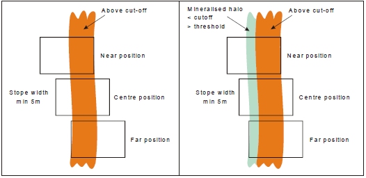
Narrow Ore Positioning Example.
Minimum Pillar Width
A pillar will separate seed-shapes or stope-shapes if the maximum stope width would otherwise be exceeded, or low grade/waste can be isolated from stope shapes.
Waste cells (representing mineralisation below cut-off, or rock without mineralisation) surrounding the ore cells are required for runs with sub-stopes, as the location of the mined-out cells is used to force the pillar width between stopes and sub-stopes, and between sub-stopes and sub-stopes.
If the stope wall angle ranges are the same for both the hangingwall and footwall, or roof and floor, then the minimum pillar width is checked at each corner. If the stope wall angle ranges are different, then the minimum pillar width is checked at the wall centre.
Note that the pillar width parameter is defined as the distance in the horizontal plane i.e. the apparent pillar width.
Strike Angle
The strike angle is the angle of any one of the four stope wall edges (measured relative to the U axis of the stope orientation plane).
Ideally the strike angles would be loosely defined (using broad tolerance range) in a preliminary test SSO run in order to give a reasonable upper limit on the number of stopes produced or to maximise the stope dimensions. The strike angle parameters would then be progressively refined as required.
One example application would be where stope-shapes are formed in a criss-crossing pattern between “parallel” lenses which have discontinuous mineralization, and the user wanted to force the stopes to not criss-cross between the lenses.
Another example would be the formation of stope-shapes that have rapid or chaotic changes in wall angles, giving the appearance of being “malformed” (but are actually not).
The above examples may be considered to be impractical stope-shapes to implement, and hence the wall strike angle changes are “smoothed” out to better approximate a mineable set of stope shapes.
The following sub-sections describe the strike angle parameters in more detail.
- Strike Angle Range
This defines the strike angle range of either edge (i.e. top or bottom) of either wall of the stope-shape (near/far wall or hangingwall/footwall wall) relative to the framework’s strike axis (the U-axis). The range can be independently defined as positive and/or negative relative to the stope shape framework strike axis. - Strike Angle Maximum Change
This defines the maximum allowable stope-shape “twist” relative to the top and bottom wall edges.
Side Length Ratio
The ratio is defined by the end-face wall lengths and the axis direction pairing being considered, described further in the following sub-sections.
Ideally the side length ratios would be loosely defined (broad range) on a preliminary SSO run to maximise the number of stopes produced or to maximise the stope dimensions. The side length ratios would then be progressively refined as required.
An example use of the side length ratio is to force walls (i.e. near/far walls or hangingwall/footwall walls) to be parallel to each other (i.e. a sectional parallelogram) so that all production hole drilling is parallel for a narrow tabular orebody. This is achieved by using a 1:1 ratio, but this ratio should only be used in a final run to ensure that all the required shapes are generated in the annealing phase. Likewise, in the U-axis direction plan view parallelograms can also be specified.
-
Side Length - vertical_side_length_ratio, top_bottom_maximum
For either top-edge divided by bottom-edge or bottom-edge divided by top-edge) and applies to either end-wall face (i.e. front or back). The upper limit for the ratio (longer/shorter) of the top and bottom edges of the front and back strike-face of a stope-shape as shown below:
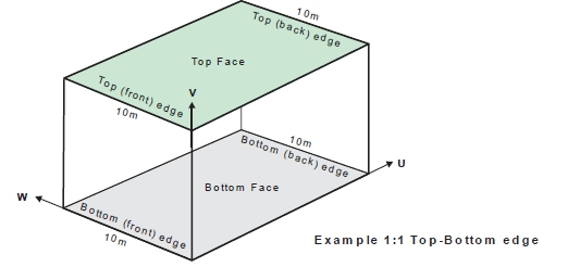
Top-edge to bottom-edge ratio (V-axis pairing)
-
Side Length - vertical_side_length_ratio, front_back_maximum
The upper limit for the ratio (longer/shorter) of the front and back edges of the top and bottom face of a stope-shape as shown below:
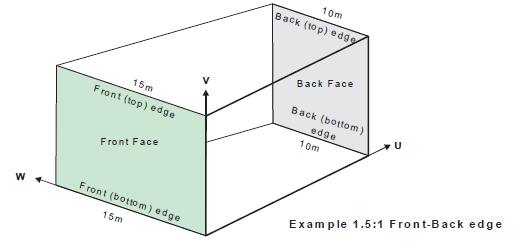
Front Edge to Back Edge Ratio (U-axis pairing)
Waste Inclusion Control
The maximum waste fraction of stope-shapes can be defined (i.e. proportion of rock with mineralisation values below specified cut-off included within the stope-shape).
The waste inclusion is defined as:
Volume of material inside diluted stope shape below cut-off
————————————
Volume of diluted stope shape
A default fraction value of 1.0 means any waste proportion is acceptable.
It is good practice to:
- Start with a test value of 1.0 and gradually refine this in subsequent runs to monitor the impact.
- If you have back-fill in the “voids” located within stope-shapes, then do not associate this material with the “report_exclusion_field”, as it should have a density and grade, and effectively be in one of the three waste categories.
Exclusion Control
The exclusion control can be used to avoid the creation of stope-shapes within say deleterious-processing material or in poor rock-mass zones as a few examples of its use. The material in the model is flagged with a (numeric or alphanumeric) field and a value.
Up to two exclusion fields can be defined in a run. Each exclusion field permits a certain maximum tolerance of inclusion within a stope-shape.
The exclusion control is defined as the maximum fractional proportion of material (by volume) in the stope-shape that is flagged as either “exclusion1” or “exclusion2” material.
The tolerance for each exclusion field “exclusion1” and “exclusion2” is set independently, and allows for a maximum fractional proportion of the respective exclusion material to be incorporated into the stope-shape. As an example, you may be mining a secondary pillar stope and the shape of the adjacent primary backfilled stopes may bulge into the secondary, so for practical purposes you may allow say up to 5% (0.05 fraction) of backfill material within the secondary stope-shape.
Related topics and information