
MSO Orientation Settings
Orientation settings control how MSO slices, aligns, and processes the block model to generate stope shapes. It determines the spatial framework MSO uses to evaluate and segment the orebody, which directly impacts the geometry of the stopes created. Each optimization method offers distinct geometry assumptions that match different deposit styles and mining methods. The tab also provides control over the direction, dip, and strike of generated slices or prisms, ensuring the output is geologically and operationally aligned.
Important concepts:
-
The model extents displayed on this panel represent the overall bounding box for the specified input model.
-
The MSO shape framework extents can be identical, but are specified independently - the Framework Extents are represented by a cuboid within which your stope shapes will be generated. Normally, the shape framework will extend beyond the extents of the model in each direction, fully encapsulating it. You can easily check this is the case using the Extents Visualization controls at the bottom of the panel.
-
Setting the primary orientation method can change some or all of the screens that follow on the right of the MSO ribbon. This is to ensure appropriate settings (only) display for the chosen orientation method. For example, Prism method Framework settings are entirely different to those of the Boundary Surface method.
You can set up independent orientation settings for each scenario that you have specified, with each scenario selectable in the drop-down list at the top of the panel.
If your input block model (or shape framework) is rotated, you can also use the Orientation screen to view the discretization plane using the Visualize in 3D function:
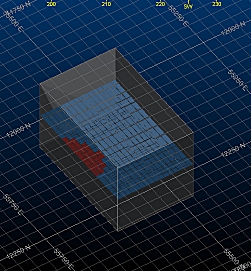
A model with loaded Framework Extents (copied from the model)
Optimization Method
Selecting an Optimization Method is key to what appears on the Orientation screen.
Selecting the appropriate optimization method is key to obtain good and practical stope shapes. More information about each method can be found at the AMS-MSO manual:
-
AMS MSO Manual – Section 4.1.1: Slice Optimization Method
Details how slice-based stopes are generated using slice thickness, orientation, and framework controls. It also explains the impact of slicing plane on stope output.
-
AMS MSO Manual – Section 4.1.2: Prism Optimization Method
Describes the use of vertical and arbitrary-axis prisms for constructing stope shapes, typically in bulk mining scenarios. Explains how prisms are aligned and the role of rotation angles.
-
AMS MSO Manual – Section 4.1.3: Boundary Optimization Method
Covers stopes constrained by a reference surface, such as a geological boundary. Includes details on surface-normal orientation and stope parallel alignment to boundaries.
Note: The MSO manual is installed with each copy of Mineable Shape Optimizer. If you are using a different Studio product and require a copy of the MSO operating manual, please contact your local Datamine office.
Summary
This part of the MSO workflow is used to:
-
Define slicing or prism orientation (for Slice, Prism, or Boundary methods).