Prism Frameworks
The Prism Method of stope shape optimization is typically applicable to massive orebodies or wide/thick deposits whose stopes tend to be designed by blocking out the orebody in a grid-like pattern.
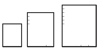
The Prism Method allows you to define a library of possible stope volumes by using permutations of stope length, width and height (as rectangular prisms). The library of stope volumes can be defined as rectangular prisms or defined as prisms with a centralised undercut trough (a shape like an inverted “milk-carton”). The stope library can be developed quickly by using minimum and maximum values (the increments are defined already using the Prism Orientation Settings screen. Alternatively, the library can be explicitly defined giving specific axis dimensions for each stope volume.
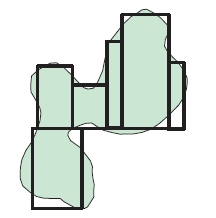
The Prism Method optimally combines the stope volumes within each framework "region" with no overlapping of either regular or various irregular stope volumes (it selects the optimum non-overlapping combination of rectangular stope volumes). The goal of the optimisation is to select the set of non overlapping stope-shapes that maximises value for the material to be extracted by the selected stope shapes. All possible combinations of shapes and positions are considered in the optimisation.
As an example, a typical goal of optimally combining stope-volumes with different dimensions (e.g. a small footprint stope adjacent to a large footprint stope) is to determine the optimal orebody footprint.
Defining a Prism Framework
To access Prism framework options, select the Orientation panel's Prism Optimization Method and other general orientation settings via the Prism Orientation Settings screen.
The Prism method is a different style of stope optimization to the Slice method. In the Slice method the stope shape framework is decomposed into individual geometric tubes based on the level and section dimension for the vertical case, and the stope shape (or sub-shape) is an optimization over the width of the orebody, with a two stage process to firstly, define the seed-shape and secondly, to anneal the final stope shape.
The Prism method also requires a stope shape framework, but uses the decomposition of the framework extents to define sub-problems. The framework extent is subdivided in regular intervals, much like regular quadrilaterals, except that the subdivision is three dimensional rather than two dimensional, and each subdivided volume is referred to as a region, whereas the Slice method subdivision is two dimensional to form a tube.
Prism frameworks are not orientation- specific but the XYZ intervals must be regular. A grid increment is defined for each axis, within regions (subset volumes of the total Prism framework). Shapes from the stope volume library will normally have dimensions that are an integer multiple of the grid increment and can result in stopes located at any grid increment.
As such, if a Prism framework has been specified, the only definition required is the intervals along the U, V and W axes to form the framework regions. For each of the U, V and W local axes, this panel is used to determine an Increment (size) and Number.
Warning: Increasing the number of sections and levels, either through decreasing the Increment or setting up a variable increment configuration can have a dramatic effect on the resulting stope-shapes, including the processing time that is required to perform a run. It is good practice to start with a coarse framework (levels and sections) and gradually increase the "resolution" of the calculation until an optimal result is acquired.
Stope Shape Dimensions
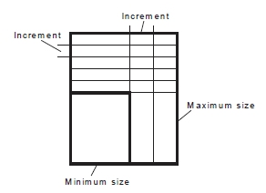
Defining dimensions for stope shapes in the Prism framework is a matter of setting stope shape sizes in the stope shape library using the Minimum and Maximum size and step increments for each axis.
Note: Minimum must be a multiple of the Axis Step for the same axis.
This method, that is, selecting a stope by a range specification, is represented by the image below:
Stope Shape Dimension List
As an alternative to defining stope dimensions per axis, you can also define dimensions per stope shape explicitly. The optimized shape combination can match the shape and position of stopes from the stope shape library to the ore outline to maximize ore extraction, and total value.
Select this option to display a table. Add or edit rows to specify
the dimensions in UVW. Setting a stope size by discrete shapes
(a subset of the range specification) allows an optimal shape
combination to be calculated.