Wedge Stability Analysis
Sirovision can perform stability analysis that is based on actual structures that have been mapped, rather than the traditional method of using orientation data alone. This method accounts for structure size, uses georeferenced data and captures the spatial distribution of hazards across different parts of the highwall.
You can input geotechnical parameters to analyse two joint orientation sets to determine whether wedges could form as a result of these intersecting discontinuities and whether they highlight on the 3D image. Each wedge is assessed for stability and properties such as wedge mass, volume and sliding vectors, which can be displayed and exported to any of the supported file formats. See Exporting Data.
Before running a stability analysis in Sirovision, orientation sets must be generated and geotechnical parameters of the rock surface must be input as domain characteristics for the rock mass. See Create Orientation Sets.
Assumptions
A wedge is only identified, and its stability analysed, if all of the following criteria are met.
- The idealised discs associated with two mapped structures intersect (one from each of the two sets selected for analysis).
- The line segment formed from the intersection of these discs falls behind the 3D image/mosaic or at least partially intersects the 3D image/mosaic.
- The down-dip sliding vector implied by the intersection daylights on the 3D image/mosaic (that is, it exits the surface from behind the face).
The following diagram shows the intersection of two discs, associated segment of intersection (bold red) and sliding vector (dotted red).

Intersecting discontinuity discs and sliding vector and segment of Intersection
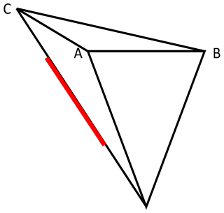
The wedge is defined using a conservative approach. The segment of intersection is used as a guide and the wedge must incorporate all of it. The figure below shows the wedge (tetrahedron) geometry for the simplest case. The segment of intersection is shown in red. The point D is defined as the point of the 3D image where the sliding vector daylights. Point C is defined as the intersection of the sliding vector and the top horizontal release plane. By default, this release plane is set to a height above point D ,equivalent to the maximum persistence of the two discontinuities defining the wedge. The user can manipulate the height of this plane by using the mouse. Points A and B are then calculated as the points on the 3D image where the vectors CA and CB intersect. If these points cannot be calculated (for example, if the top of the wedge is above the 3D image), then A and B are calculated assuming the face of the wedge is vertical and anchored at D (that is, triangle ABD lies on a vertical plane).

Geometry for a tetrahedral wedge and segment of intersection
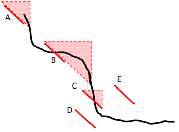
A conservative approach has also been adopted for some of the less obvious wedges that can form given the above criteria. The diagram below summarises these. It shows a section of a 3D image and the various possibilities for the position of a calculated intersection segment. The following table summarises the logic used to determine if a wedge would be identified and how that is achieved for each case.

| Case | Result |
|---|---|
| A |
Wedge forms due to daylighting sliding vector, point D on 3D image. |
| B |
Wedge forms due to daylighting sliding vector, point D on 3D image |
| C |
Wedge forms due to daylighting sliding vector, point D on end of segment. |
| D |
Wedge does not form as sliding vector does not daylight. |
| E |
Wedge does not form as sliding vector does not daylight. |
Wedge Classification Scheme
For wedges identified using the above criteria, a stability analysis is performed using the limit equilibrium method (two-plane sliding) as described in Hoek E. and Bray J.W. (1981) Rock Slope Engineering, Revised 3rd edition, The Institution of Mining and Metallurgy, London. The calculation considers the friction angles and cohesions of the sliding surfaces as well as the user-specified pore-pressure forces.
The wedge shape (tetrahedron), volume and mass are determined assuming a horizontal release plane exists. You can control the elevation of this release plane.

