
Topography Mode Example
Note: This topic relates to the Dynamic Modelling Properties control bar.
When the Dynamic Modelling workflow is processed, a topography can be set as one of the data extents.
You use the Dynamic Modelling Properties control bar to determine how a block model task is performed, with respect to each topography.
The following options are available:
-
Fill below – Create model cells below the topography only. Cells are only created if they fall directly below the surface(s).
-
Deplete above – Remove cells of the prototype directly above the topography data.
Where a topography fully intersects the specified prototype model, the results of both are the same (data appears below the topography, with cells filling the cuboid up to the specified modelling extents.
Where a topography only partly intersects a topography, however, it becomes more import to pick the right option.
Here's why:
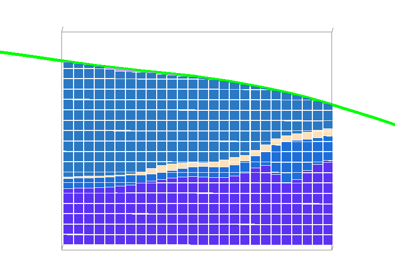
Consider the following example, where a topography fully intersects the prototype model used to constrain data. In this example, the prototype is unrotated and is fully contained within the vertical 'shadow' of the topography:
In this situation, either Fill Below or Deplete Above generate the same block model result:
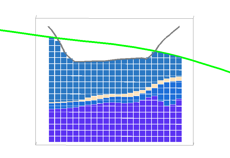
A different topography is added to the same workflow; a pit shell, shown as a grey line below. The pit shell only partly intersects the prototype model:

In this case, if the Fill below option is set for the pit shell (meaning both topographies have the same setting, the resulting block model is incorrectly depleted. The cells that don't lie directly below it are removed from the final model. This would give rise to incorrect volumes and inappropriate grade and tonnage analysis:
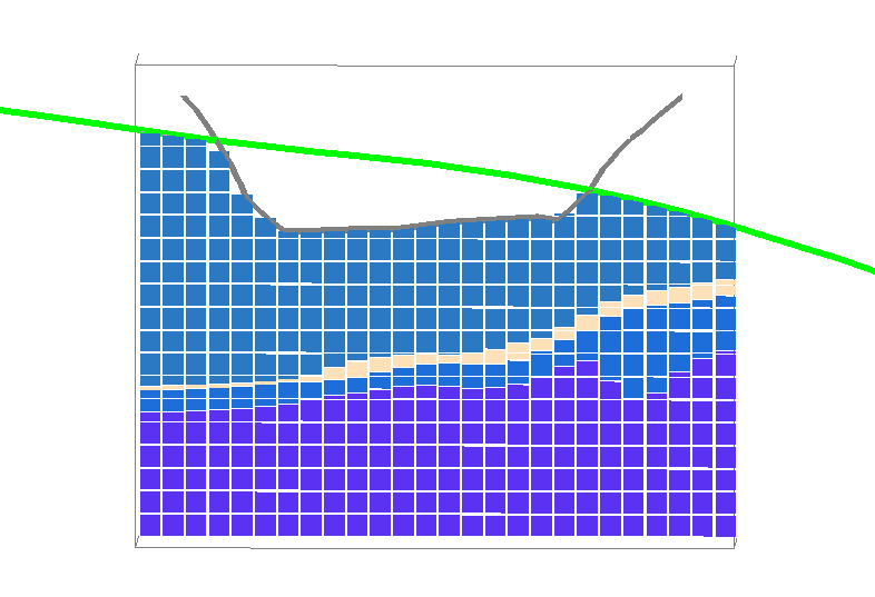
If the Deplete above option is picked for the partly-intersecting pit shell, the result is more likely to be correct, as in this case, the model within the pit shell is removed from the final model, leaving the cells below it intact:
Related topics and activities